

Ultrasonic Flow Monitoring in Industrial Liquid Cooling Systems
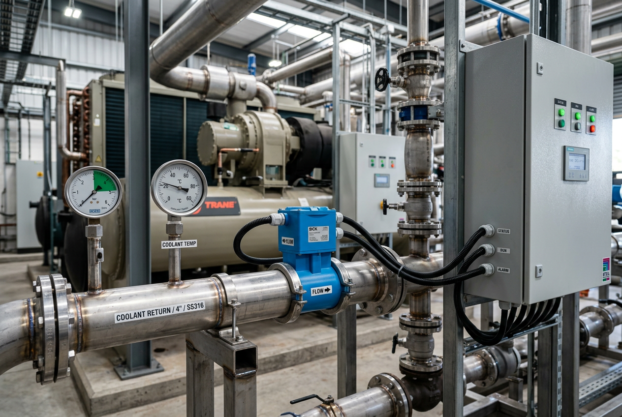
Ultrasonic Flow Monitoring in Industrial Liquid Cooling Systems
How non-intrusive flow measurement helps operators monitor coolant circulation, protect thermal performance, and identify cooling anomalies.
Why Does Real-Time Coolant Flow Monitoring Matter in Industrial Systems?
Industrial cooling systems remove concentrated heat from mission-critical equipment to maintain safe operating temperature thresholds. Typical applications span high-density data center liquid cooling, industrial water chillers, semiconductor processing loops, and high-performance computing (HPC) infrastructure.
When coolant circulation drops below design thresholds, heat transfer efficiency rapidly declines, causing thermal throttling, component stress, or catastrophic equipment shutdown. Conversely, excessive flow wastes pumping energy, increases hydraulic shear, and accelerates pipe erosion without delivering proportional thermal improvements. Reliable, continuous flow measurement enables engineering teams to understand dynamic circuit performance across varying ambient and thermal loads.
How Does Ultrasonic Flow Measurement Operate in Liquid Cooling Loops?
Ultrasonic flow sensors evaluate fluid movement by transmitting acoustic sound pulses through the liquid conduit and analyzing how the signal propagates. Modern devices primarily utilize two distinct measurement methodologies:
Transit-Time Ultrasonic Measurement: Highly effective in clean liquids (such as deionized water, chilled water, and treated water-glycol mixtures). The device measures the time differential between ultrasonic acoustic pulses traveling upstream versus downstream. Precision instruments like the Dynasonics TFXL Series Ultrasonic Flow Meter utilize transit-time technology to deliver non-invasive volumetric flow rates without inducing pressure drops or requiring pipe penetration.
Doppler Ultrasonic Measurement: Employs acoustic frequency shifts reflected from suspended acoustic reflectors, bubbles, or suspended solids in the fluid stream. While useful in aerated or slurry environments, transit-time remains the industry standard for closed-loop industrial coolant systems.
When Should Engineers Select Non-Intrusive Clamp-On Sensors?
Non-intrusive clamp-on ultrasonic sensors attach directly to the exterior of existing piping without requiring pipe cutting, tapping, or shutoff valves. This provides several operational advantages:
Zero Wetted Mechanical Parts: Eliminating internal impellers, turbine blades, or vortex shedding bars removes mechanical wear points and prevents sensor fouling from mineral scale or biological buildup.
Zero Added Pressure Loss: Pumping efficiency is preserved, which is particularly vital in low-pressure secondary cooling loops and direct-to-chip cooling loops where available head is strictly constrained.
Elimination of Leak Points: In sensitive computing facilities and electrical switchgear environments, avoiding inline pipe penetrations eliminates the risk of coolant leaks at sensor joints.
Installation Tip: Always confirm pipe acoustic properties and wall thickness. While clamp-on transducers suit standard stainless steel, copper, or PVC pipes, lined or heavily scaled conduits may require dedicated spooled inline ultrasonic flow tubes.
Where Are the Most Critical Flow Monitoring Locations in a Cooling Circuit?
Deploying flow sensors strategically across hydraulic circuits enables targeted diagnostics rather than broad plant-level assumptions. Key monitoring locations include:
- Main Supply & Return Headers: Tracks bulk volumetric circulation from primary chillers and plate heat exchangers to evaluate overall facility pumping health.
- Coolant Distribution Units (CDUs): Verifies secondary loop flow balancing and differential pressure matching across primary/secondary decoupled loops.
- Branch Distribution Manifolds: Monitors fluid balance across server racks, furnace induction coils, or individual injection mold cooling channels.
- Bypass Lines & Balancing Valves: Identifies unwanted short-circuit flow through three-way valves or faulty check valves.
How Do You Integrate Ultrasonic Flow Sensors into PLC and DCS Architectures?
Ultrasonic transmitters deliver actionable measurement data to industrial controllers via standard 4–20 mA current loops, high-speed pulse/frequency outputs, or digital fieldbuses (Modbus RTU, BACnet, or EtherNet/IP).
In ControlLogix and CompactLogix architectures, high-frequency pulse trains can be ingested directly into specialized flow interface modules like the Allen-Bradley 1756-CFM ControlLogix Configurable Flowmeter Module or multi-channel pulse counter cards like the Allen-Bradley 1756SC-CTR8 8-Channel Counter Module. When liquid thermal capacity and custody-level energy accounting (BTU calculation) are required across varying temperatures, an integrated flow computer such as the Rockwell Prosoft MVI56E-AFC Flow Computer provides instantaneous mass flow and heat transfer computation directly on the PLC backplane.
The PLC compares instantaneous flow against pump speed (VFD feedback), supply/return differential temperature (ΔT), and heat load. Cross-referencing these data streams enables automated variable-speed pump staging and rapid leak-detection interlocks.
What Abnormal Cooling Conditions Can Flow Data Help Diagnose?
Continuous flow telemetry allows maintenance engineers to quickly diagnose common liquid cooling anomalies before thermal tripping occurs:
- Cavitation & Air Ingress: Entrained microbubbles attenuate acoustic ultrasonic signals, causing sensor signal-quality metrics to drop before mechanical pumps suffer impeller cavitation damage.
- Partial Line Restrictions: Gradual flow decay at constant pump RPM highlights particulate strainer clogging or scale accumulation within cold plates.
- Hydraulic Imbalance: Uneven flow across parallel cooling loops reveals improper valve trimming or thermal siphoning effects.
- Sudden Line Rupture: A rapid mismatch between supply header flow and return header flow instantly triggers emergency isolation solenoid valves.
How Should Maintenance Teams Validate Flow Sensors in the Field?
Achieving reliable ultrasonic measurement requires thorough field commissioning and parameter verification:
- Coolant Fluid Parameter Matching: Water-glycol blends (e.g., 30% or 50% ethylene/propylene glycol) have significantly different sound velocities and kinematic viscosities compared to pure water. Always configure the transmitter with exact fluid concentration and operating temperature curves.
- Straight-Run Pipe Compliance: Ensure adequate upstream (typically 10 diameters) and downstream (5 diameters) straight pipe runs free of elbows, valves, or reducers to maintain fully developed turbulent flow profiles.
- Acoustic Coupling Gel Verification: For clamp-on sensors, check that acoustic couplant has not dried out or degraded under thermal cycling. Use high-temperature silicone couplant for permanent installations.
- Signal Scaling & Alarm Validation: Test zero-flow calibration during pump shutdown and verify 4–20 mA / pulse scaling across minimum, nominal, and maximum design flow ranges.
Summary & Practical Action Advice: How Should Operations Teams Proceed?
Ultrasonic flow monitoring provides vital operational visibility into industrial liquid cooling and chiller circuits without intrusive pipe modifications or added pressure losses. By pairing clamp-on ultrasonic meters with dedicated PLC flow input modules, facilities can detect air entrapment, balance secondary branches, and safeguard high-value thermal assets against unplanned downtime.
Article contributed by Lin Wei, Senior Industrial Automation & Process Instrumentation Specialist at PLC DCS Pro Ltd.


