

Spurs, Trunks, and Terminators: Building a Foundation Fieldbus Junction Box the Right Way
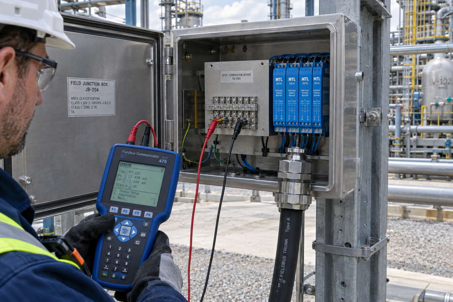
An installation review based on the instrumentationtools.com article "4-20mA Junction Box versus Fieldbus (FF) Junction Box".
Q: How is an FF junction box different from a 4-20mA junction box?
A conventional junction box contains a terminal strip, such as a Phoenix Contact MTK knife-disconnect terminal block, and an earth bar. Field pairs land on one side, multipair home-run cables leave for the marshalling cabinet on the other, and shields terminate per project philosophy. Each pair is independent, so one shorted pair spoils one loop.
A Foundation Fieldbus junction box carries a network segment. Expect spur boards with barriers, a trunk termination assembly, surge protection, and a terminator. One bad connection can take down a dozen instruments, so staff FF installs with people trained on segment physics, not just terminal tightening.
Q: Which cable is the spur and which is the trunk?
The cable from a field instrument is the spur. The cable toward the control system, for example a Yokogawa ALF111-S50 FOUNDATION Fieldbus communication module or an Allen-Bradley 1788-EN2FFR linking device, is the trunk. In a High Power Trunk design, the trunk is non-IS and the spurs are intrinsically safe, and that mixed condition drives the whole enclosure layout.
Q: Can I re-route the internal wiring on site?
No. The trunk termination assembly is isolated by a separator plate, and IS and non-IS circuits must not share space or terminals. The supplier wires the box at the factory as part of the certified assembly. The field engineer terminates only spur and trunk cables at the boards.
Q: How many terminators does a segment need?
Exactly one at each physical end, and only at the ends. Foundation Fieldbus is a Manchester-encoded bus and reflections kill it. Two terminators at one end degrade the signal as badly as none.
Q: Why does surge protection matter so much?
A spur climbing a tower or crossing a tank farm invites lightning-induced transients. A device such as the Phoenix Contact TTC-6P-1X2-M-24DC-UT-I surge protector sits ahead of sensitive barrier electronics like the MTL5516c isolated barrier. Build the box to the approved segment drawing, and never add a spur just to make a job fit.
Q: Can I put temperature multiplexers on a Fieldbus segment?
Yes. The multiplexer mounts in its own box and connects to the FF junction box as one spur, like a transmitter. Limit each segment to one or two multiplexers, because they poll slowly and too many stretch cycle time. On a Yokogawa CENTUM project I commissioned, three multiplexer boxes on one segment produced uneven scan rates. Rebalancing to two per segment fixed it in an afternoon.
Q: What is the right termination sequence?
- Verify the segment drawing: spur count, cable lengths, terminator positions, device addresses.
- Inspect the separator plate so IS spurs and non-IS trunk stay divided.
- Land the trunk first, torque the glands, and confirm shield and continuity.
- Fit the terminator at one segment end only, then check bus voltage.
- Terminate spurs on the barrier boards, observe polarity, never mix barrier channels.
- Commission with a communicator: wave shape, device count, and noise margin.
Q: What maintenance keeps segments alive?
Fieldbus faults hide in mechanics. Loose glands, water ingress, and gland plate corrosion all distort the waveform. Check breather plugs and drain paths in humid sites, verify barrier modules are the correct type, and keep a spare spur board and terminator set on the shelf. Document every change, because adding one instrument alters power budget and length.
Conclusion and Action Advice
An FF junction box is network hardware inside an enclosure. Respect the separator plate, terminate once at each segment end, honor the one-to-two multiplexer limit, and commission with wave-shape evidence. For background, see the instrumentationtools.com comparison article and the FieldComm Group Foundation Fieldbus specifications.
Author: He Jingchuan is an industrial automation engineer with over 10 years of experience in PLC, DCS, and control systems.


