

Clean Earth, Quiet Signals: ABB and Phoenix Contact Best Practice for Instrument Earthing
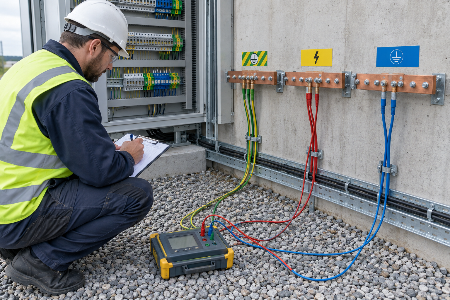
Instrument earthing has three jobs: protect people, manage fault and lightning energy, and keep measurements dependable. This commissioning review draws on Instrumentation Tools’ discussion of good earthing practice. Apply the approved site drawings, applicable electrical and hazardous-area standards, and each device manufacturer’s instructions before changing any bond.
Why can poor earthing show up as noisy signals?
Unintended current paths, damaged connections, and shield-termination mistakes can contribute to unstable analog readings or communication faults. They are possible causes, not a diagnosis on their own. When troubleshooting an ABB 800xA installation, compare observed symptoms with the approved bonding diagram and inspect the connections before replacing electronics such as the ABB 800xA PM861A processor.
How should power, lightning, and instrument earthing be planned?
Identify protective earth (PE), lightning protection (LPS), and instrument or functional earth (IE) separately on drawings and label their test points. Their physical layout and interconnections must follow the engineered site design. Do not assume that separate rods or a single bonding point are correct for every installation: safety, equipotential bonding, EMC, and lightning requirements can call for different arrangements. Record the approved resistance and continuity acceptance criteria rather than using one universal target.
Do galvanic isolators eliminate intrinsic-safety earth requirements?
Not automatically. A certified galvanic isolator may avoid the dedicated high-integrity earth connection required by some Zener-barrier arrangements, but the exact requirement depends on the device certification, installation drawing, circuit design, and local rules. Before replacing barriers, check entity parameters, separation, wiring, supply capacity, and the hazardous-area assessment. Do not remove an existing IS bond just because the replacement is described as galvanically isolated.
What should commissioning engineers check?
- Compare rod locations, conductors, connections, and labels with approved as-built drawings.
- Measure earth resistance and continuity using the specified method and project acceptance limits; document the instrument, date, conditions, and results.
- Check for unintended bonds and inspect every accessible termination without disconnecting a protective conductor in service.
- Verify analog and Profibus DP shield termination against the system and cable manufacturer’s instructions. Do not apply a blanket one-end-only rule to every fieldbus shield.
- Repeat inspections after alterations, damage, or severe weather as required by the maintenance plan.
What should a noisy-loop investigation conclude?
Profibus retries, analog drift, and unexplained trips warrant investigation, but none proves an earthing fault by itself. Trend the symptom, inspect connectors and shield terminations, measure the relevant paths safely, and compare findings with the drawings. For an ABB panel upgrade involving a SC540 submodule carrier, document any wiring or bonding change before returning the system to service.
Takeaway: Keep PE, LPS, and IE clearly identified, verify their engineered bonding scheme, and maintain a test register. Quiet signals start with measured, documented connections, not a universal earth-pit recipe.
Author: Wang Junjie, industrial automation engineer.


