

PLC Panel and MCC Panel Interface Signals Explained
What Is a PLC Panel?
A PLC panel is a control unit housing a Programmable Logic Controller and its supporting components. It includes circuit breakers, relays, SMPS, filters, transformers, and terminal boards.
Its job is simple: connect field devices to the PLC and execute logic stored in the CPU. Since it handles low-power control signals, it must remain free of heavy current devices. Mixing high-frequency loads inside can create noise and even damage sensitive PLC electronics.
What Is an MCC Panel?
An MCC (Motor Control Center) panel handles the heavy electrical side of motor operation. It contains busbars, contactors, thermal overload relays, soft starters, VFDs, and power switches.
MCC panels allow motors to run in local mode (controlled at the panel) or remote mode (controlled by PLC). This design separates high-current wiring from the PLC panel, simplifying installation and troubleshooting.
For plants with many motors, MCC panels reduce wiring complexity and improve system reliability.
Why Interface PLC and MCC Panels?
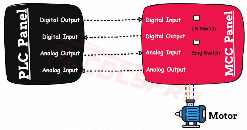
In automation, PLC and MCC panels must “talk” to each other. The MCC sends motor feedback signals, while the PLC sends control commands.
This two-way communication ensures motors respond to automation logic, while operators monitor conditions in real time. The goal is seamless integration between field-level motor control and logic-driven automation systems.
Common Interface Signals
- Start Command: Pulse signal from PLC to MCC to start the motor.
- Stop Command: Pulse signal from PLC to MCC to stop the motor.
- Run Feedback: Input to PLC showing motor running status.
- Trip Feedback: Input to PLC indicating fault or trip condition.
- Local/Remote Feedback: Signal showing if motor runs locally or remotely.
- Emergency Switch Feedback: Input showing if the E-stop has been pressed.
- Control Switch Feedback: Input showing whether control power is ON.
- Motor Speed Feedback: Analog signal from VFD/soft starter showing motor speed.
- Motor Speed Control: Analog output from PLC to VFD to adjust motor speed.
Practical Example
Imagine a conveyor system running ten motors. Each motor connects to its MCC starter, while the PLC coordinates all motors together.
If one motor trips, the MCC sends a trip feedback to the PLC. The PLC then stops the upstream conveyor automatically, preventing product jams.
This real-time coordination is why the PLC–MCC interface is essential in modern plants.
Final Thoughts
The interface between PLC and MCC panels is more than just wiring. It represents a bridge between logic and power in industrial automation.
With proper signals for start, stop, feedback, and speed control, systems run safely and efficiently. Understanding this relationship allows engineers to design more reliable and maintainable plants.
When in doubt, choose quality components and proven integration strategies—your motors and operators will thank you.


