

4–20 mA and HART Loop Checks: A Practical Field Commissioning Guide
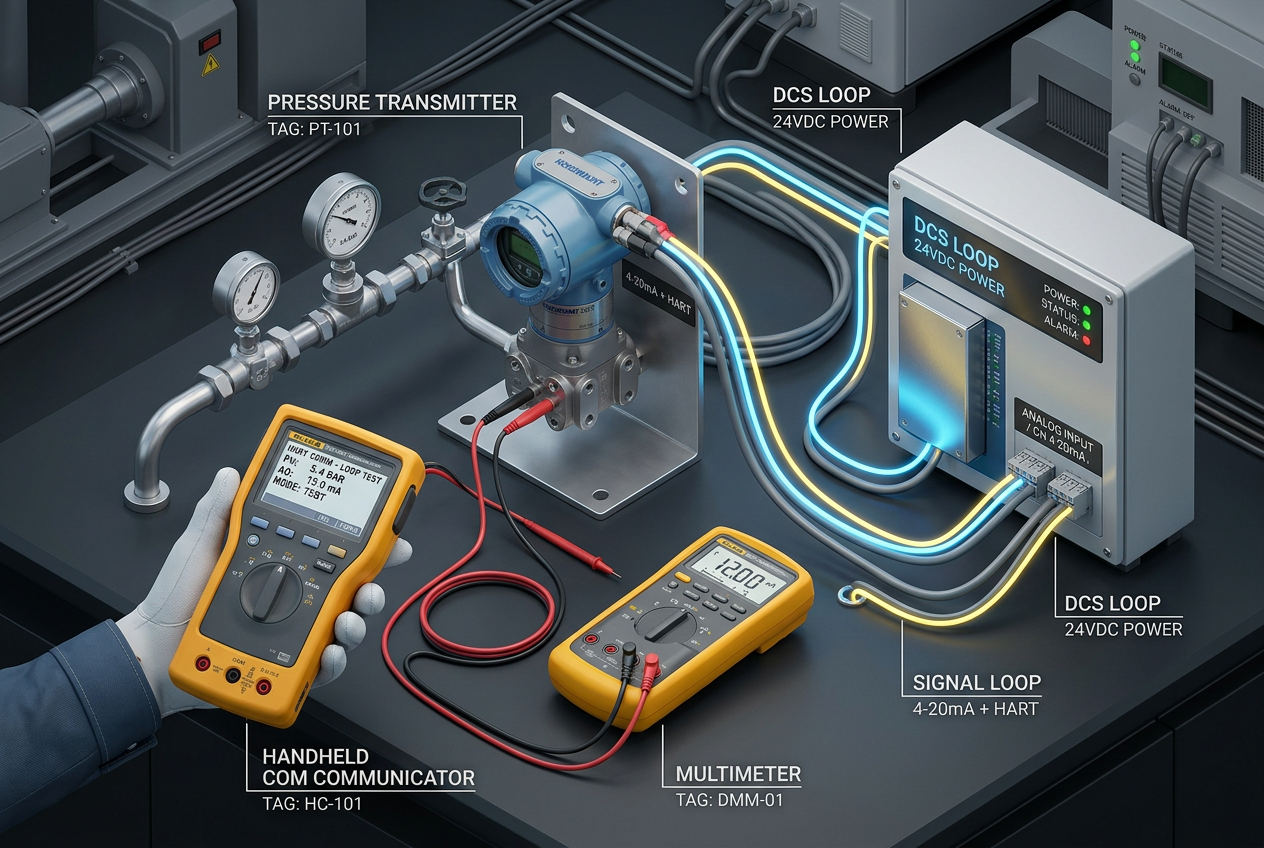
4–20 mA and HART Loop Checks: A Practical Field Commissioning Guide
Verify the field instrument, analog circuit, and PLC or DCS indication with a controlled test sequence.
Q1: What does a 4–20 mA and HART loop check actually verify?
A standard 4–20 mA current loop consists of a field transmitter, a 24V DC loop power supply, field cabling, and one or more receiving devices, such as a PLC analog input card, a DCS channel, a local panel indicator, or a safety isolator. HART technology superimposes digital FSK communication over the same analog loop.
A loop check confirms that signal transmission, circuit wiring, and control system scaling are properly aligned. However, the exact test method determines what is verified: forcing a transmitter's mA output tests the cabling, loop impedance, and DCS I/O processing (such as on an Emerson DeltaV KL3021X1-LS1 HART Analog Input CHARM Module), but it does not test the physical primary sensor or process impulse line. Always review the loop diagram to distinguish between 2-wire (loop-powered) and 4-wire (self-powered) active/passive circuits before connecting test equipment.
Q2: How should electrical checks and current measurements be conducted safely?
Systematic electrical verification prevents burnt fuses and false diagnostic alarms. Follow these sequential checks:
- Verify Loop Supply Voltage: Measure DC voltage across transmitter power terminals under full load. Ensure the net voltage exceeds the transmitter's minimum operating voltage after deducting line loss and receiver burdens through interface barriers like the MTL4541B Repeater Power Supply.
- Inspect Field Cabling and Polarity: Verify wire labeling, terminal block torque, and overall shielding continuity. Ground the cable shield at one point only (typically at the control cabinet) to avoid circulating ground loops.
- Measure In-Series Current Accurately: Use a calibrated digital multimeter in mA series mode, utilizing dedicated test diodes or test jacks where provided. Never place a current-configured meter across a live voltage supply.
- Execute Stepped Output Testing: Command the transmitter or signal generator to output 4 mA (0%), 8 mA (25%), 12 mA (50%), 16 mA (75%), and 20 mA (100%), following Rosemount and Emerson standard commissioning procedures.
- Cross-Check Control System Readings: Verify that the raw current corresponds accurately with the engineering display in the PLC or DCS, checking modules such as the Emerson Fisher-Rosemount KJ3002X1-BC1 AI Module or DeltaV KJ3221X1-BA1 AO HART Card.
Q3: How do you verify linear scaling and process signal interpretation?
For standard linear transmitters, the displayed engineering value is calculated directly using the lower range value (LRV) and upper range value (URV):
Engineering value = LRV + ((I − 4) / 16) × (URV − LRV)
Where I is the measured loop current in milliamperes. For example, on a pressure transmitter calibrated for 0 to 100 bar, a 12 mA signal must indicate exactly 50 bar. When readings mismatch despite accurate loop current, check whether the controller channel has applied square-root extraction (common in DP flow measurement), digital damping filters, or incorrect engineering unit tags.
Q4: How do you troubleshoot common HART communication and impedance issues?
HART digital communication requires specific physical loop conditions that differ from basic DC current loops:
- Communicator fails to detect device: Verify that total loop resistance falls between 250 and 1100 ohms. If total loop impedance is below 250 ohms, insert an external 250-ohm resistor in series so the HART FSK frequency signal can modulate properly.
- Intermittent communication dropouts: Check for excessive electrical noise, poor cable shielding, or unshielded variable frequency drive (VFD) conduits running parallel to analog signal cables.
- Digital and analog values disagree: Ensure the digital primary variable (PV) matches the analog 4–20 mA DAC calibration. If they diverge, execute a D/A trim according to the transmitter instruction manual.
- Integration with specialized PLC gateways: When routing HART multi-drop data to industrial controllers via interfaces such as the Prosoft PLX51-HART-4I HART Input Module, verify that device poll addresses and communication baud rates are harmonized.
Q5: What safety protocols are required when testing live process control loops?
Manipulating analog signals on an operating plant can cause unexpected valve movements or safety shutdowns. Always apply strict change procedures:
- Obtain operations sign-off and place the relevant PID control loop in 'Manual' mode prior to signal simulation.
- Notify control room operators before testing high or low process alarms and interlocks.
- Document as-found vs. as-left current measurements and scaling values at 0%, 50%, and 100% of span.
- Ensure all temporary simulation jumpers, meter connections, and forced override values are cleared.
- Return loops to 'Auto' mode under operator supervision and confirm live dynamic tracking.
Summary: What is the golden rule for 4–20 mA loop commissioning?
Treat the loop check as a step-by-step verification of four distinct elements: sensor response, transmitter conversion, field loop cabling, and controller software scaling. Isolating each section methodically ensures commissioning accuracy, protects equipment from miswiring, and guarantees dependable process automation.


