

Why 24VDC Power Supply Quality Determines PLC I/O Accuracy: An Allen-Bradley and Schneider Field Analysis
The Hidden Link Between DC Power and Signal Integrity
Every PLC analog input module depends on a stable 24VDC supply for accurate signal conversion. When ripple voltage exceeds 50 mV peak-to-peak on the DC bus, the internal ADC reference drifts. This drift causes a 4-20 mA reading to shift by 0.5% to 2% of span before any alarm triggers.
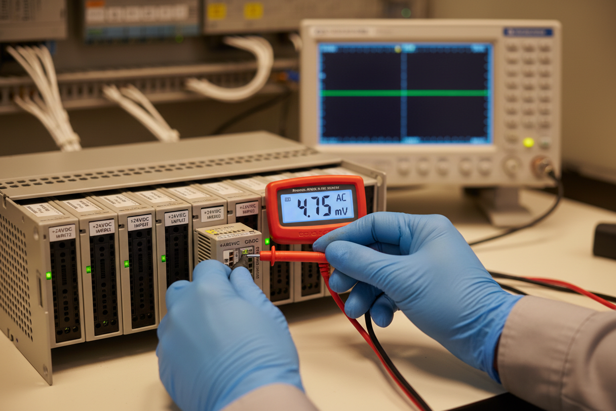
First, measure the 24VDC rail at the PLC backplane terminals using a true-RMS multimeter in AC millivolt mode. A healthy industrial power supply delivers DC voltage between 23.5V and 24.5V with AC ripple below 30 mV RMS. Second, check the power supply loading percentage. Most 24VDC supplies lose regulation above 80% rated load. An Allen-Bradley 1756-PA72 power supply driving a full ControlLogix chassis with sixteen 1756-IF16 analog modules draws approximately 4.2A at 24V. This load sits at 70% of the supply rating, leaving adequate headroom. However, adding field transmitters powered from the same rail pushes the load past the safe threshold.
Step 1: Disconnect all field wiring from the analog input module terminals. Use a precision 4-20 mA calibrator to inject a known 12.000 mA signal directly at the module.
Step 2: Read the scaled value in RSLogix 5000 or Control Expert. A 1756-IF16 configured for 4-20 mA with 0-100% engineering units should display exactly 50.00% with 12.000 mA input.
Step 3: Turn on field power to the 2-wire transmitters and compare readings. If the value shifts more than 0.25%, suspect a ground loop or power supply coupling.
HART-Based Diagnostics Reveal Power Quality Issues
Modern HART-enabled transmitters provide a powerful diagnostic layer for power supply troubleshooting. An Emerson 3051S pressure transmitter reports its terminal voltage on HART Command 48. A Schneider Modicon M580 with a BMXART0814 HART analog input module can read this secondary variable directly through the FDT/DTM interface in Control Expert.
Moreover, the HART communication signal rides on top of the 4-20 mA DC current loop as a frequency-shift-keyed (FSK) signal at 1200 Hz and 2200 Hz. A noisy 24VDC supply modulates these frequencies, causing HART communication failures long before the 4-20 mA signal shows visible errors.
Therefore, if you observe "HART device not found" errors in the DTM browser but the 4-20 mA value reads correctly, immediately suspect power supply ripple exceeding the 100 mV HART specification limit. An oscilloscope measurement across the transmitter terminals tells the full story. Set the scope to AC coupling at 500 mV/division with a time base of 2 ms/division. A clean trace shows a flat line with negligible noise. A failing power supply produces a sawtooth waveform at twice the line frequency, typically 100 Hz or 120 Hz.
Real-World Failure Mode: The Ground Loop Trap
A refinery upgrade project recently exposed this exact failure mode. The team installed twenty-four Allen-Bradley 1756-IF16 modules across three ControlLogix chassis for tank farm level monitoring. All 2-wire radar transmitters shared a single 24VDC bulk supply rated at 40A. The supply voltage measured 24.1V at the output terminals. However, the voltage at the furthest transmitter dropped to 21.8V under load — below the transmitter minimum operating voltage of 22.0V.
First, the team split the field power into four 10A circuits with individual fusing. Second, they installed Schneider XUWE2401 DC power conditioners at each remote I/O marshalling cabinet. These conditioners filter AC ripple below 10 mV and boost voltage to a regulated 24.0V at up to 3A per channel.
The results were immediate:
- Analog reading accuracy improved from ±1.2% of span to ±0.15% of span
- HART communication reliability jumped from 78% to 99.8% success rate across all 96 transmitters
Finally, the team added power quality monitoring to the DCS alarm list using the Emerson AMS Device Manager. A voltage deviation beyond ±5% on any transmitter now generates an early-warning alert.
Conclusion & Action Advice
Power supply quality is the foundation of accurate PLC I/O measurements. Audit every 24VDC rail in your control system with a true-RMS meter and an oscilloscope at least once per year. Separate field instrument power from backplane power using dedicated supplies or power conditioners. Configure HART terminal voltage monitoring on all critical loops.
A 24VDC supply that measures correctly at the source may deliver inadequate voltage at the load. The difference between a stable 24.0V and a sagging 21.5V equals the margin between process safety and a nuisance trip.
Author: Li Hongbo is an industrial automation engineer with over 10 years of experience in PLC, DCS, and control systems.


