

Triconex SIS and Emerson ASCO Solenoid Valves: Practical Integration for Emergency Shutdown Systems
What Is a Solenoid Valve in a Safety Instrumented System?
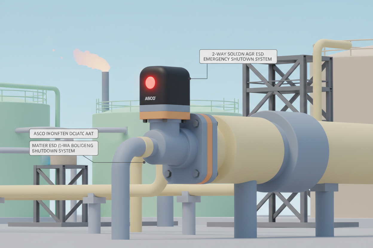
A Solenoid Valve (SOV) in a Safety Instrumented System (SIS) controls the air or hydraulic supply to automated on/off valves and Emergency Block Valves (EBV). When the Safety PLC detects a dangerous condition, it de-energizes the solenoid. This vents the actuator and causes the valve to trip to its fail-safe position. This behavior is called de-energize-to-trip.
In most oil & gas and chemical plants, the SIS operates independently from the Basic Process Control System (BPCS). The Triconex safety controller (by Schneider Electric) and Emerson ASCO SOVs are industry-standard pairings in this architecture.
SIS SOV Requirements in Detail (IEC 61511 / ISA-84)
The IEC 61511 standard sets strict requirements for SIS solenoid valves. First, the SOV must be certified to the appropriate Safety Integrity Level (SIL). Second, the valve must be direct-acting (spring-return) to guarantee fail-safe behavior on loss of power. Third, the probability of failure on demand (PFD) must meet the target SIL level.
For a SIL 2 application, the combined PFD of the transmitter, Safety PLC, and SOV should stay below 0.01. For SIL 3, the target PFD drops below 0.001. Emerson ASCO's Series 8210 and 8260 valves are commonly used for SIL 2 loops when properly designed.
Moreover, you must separate SIS wiring from BPCS wiring. Run separate cable trays. Use shielded cable for the SOV circuit to prevent electrical noise from triggering spurious trips.
Step-by-Step Wiring and Configuration
Here is the practical field procedure for wiring an Emerson ASCO SOV to a Triconex controller output module:
- Step 1 — Identify the output channel. Locate the Triconex discrete output module. Confirm the channel is rated for 24 VDC and current rating ≥ 500 mA for the ASCO coil. The DO Output Module DO3401 Invensys Triconex and the Triconex 3625 Digital Output Module are proven choices for SIS SOV circuits.
- Step 2 — Wire the SOV coil. Connect the positive lead to the DO channel positive terminal. Connect the negative lead to the 24 VDC return bus. Install a free-wheeling diode across the coil terminals to suppress inductive kickback.
- Step 3 — Configure the output in TriStation 1131. Set the output mode to "De-energize on trip" for fail-safe operation. Program the trip setpoint in the Safety PLC logic. Assign the channel to the relevant trip element (e.g., high-high pressure PSAHH).
- Step 4 — Add redundancy (1oo2 voting). For higher SIL targets, use two SOVs in series (1oo2). The Triconex dual-output module drives both coils simultaneously. Either SOV failing open causes a trip. The Triconex 9662-810 DO Termination Panel supports 16-point 24 VDC wiring for multi-SOV configurations.
- Step 5 — Validate the circuit. Perform a forced simulation test. Inject a trip signal from the Safety PLC. Confirm the SOV de-energizes and the EBV closes within the specified Safety Shutdown Time (SST), typically ≤ 2 seconds for turbomachinery protection.
How to Improve SIS Solenoid Valve Life in the Field
Solenoid valve failure is a leading cause of spurious trips in Safety Instrumented Systems. A spurious trip costs a 100,000-barrel-per-day refinery approximately $500,000 per event. Therefore, extending SOV life directly improves plant reliability and profitability.
First, apply 85% of rated voltage to the coil rather than full voltage. This reduces coil heating by approximately 28% and doubles the thermal life of the coil winding. Second, install the SOV in a location where ambient temperature stays below 55 °C. Third, use a filtered supply to prevent pressure spikes above the rated pressure of the valve. Fourth, perform semi-annual partial stroke testing (PST) on EBVs to verify valve responsiveness without taking the loop out of service.
Troubleshooting Common SOV Failures in Triconex SIS Loops
When a Safety PLC triggers a trip but the valve does not respond, technicians should check the following in sequence. First, measure 24 VDC at the SOV terminal with a multimeter. If voltage is present, the coil is open-circuit — replace the coil. Second, if no voltage appears, check the Triconex output module LED. A solid green LED means the module is energized; an amber LED indicates a field fault. Third, verify the cable integrity using a continuity tester. A broken shield drain wire in the shielded cable can cause intermittent operation. Fourth, inspect the SOV manual override. If the manual reset was not returned to auto after maintenance, the valve will not respond to electrical commands.
Conclusion and Action Advice
The integration of Emerson ASCO solenoid valves with Triconex Safety PLCs forms the backbone of Emergency Shutdown systems across the process industries. Proper wiring, SIL verification, and a disciplined maintenance schedule for partial stroke testing are non-negotiable for safe, reliable plant operation.
Action advice: Review your current SOV wiring diagrams this week. Verify that all SIS solenoid valves are connected to dedicated Safety PLC outputs. If any SOV shares a circuit with the BPCS, initiate a change management request immediately. Spurious trips are avoidable.


