

Siemens S7-300 PLC Fault Diagnosis: Step-by-Step Troubleshooting Guide
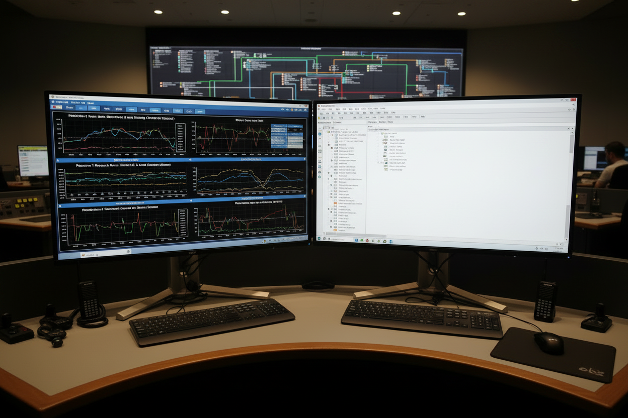
Master software errors and hardware faults with proven diagnostic techniques
Understanding Common Siemens PLC Faults
Siemens S7-300 PLCs deliver reliable automation control across manufacturing industries. However, even robust systems encounter faults. Software errors often stem from programming logic issues. Hardware faults typically arise from module failures or communication breakdowns. Understanding fault categories speeds up troubleshooting significantly.
First, identify whether the fault originates from software or hardware. Siemens PLCs generate specific error codes for each fault type. The diagnostic buffer stores detailed fault information. Access this buffer through STEP 7 software or the PLC front panel LEDs. Moreover, systematic fault isolation prevents unnecessary module replacements.
Step-by-Step Diagnostic Procedure
Follow this proven troubleshooting workflow for Siemens S7-300 PLC systems:
- Step 1: Check the CPU LED indicators first. A solid red SF LED indicates a system fault. A flashing red indicates diagnostic events requiring immediate attention.
- Step 2: Connect STEP 7 software and access the diagnostic buffer. Navigate to PLC > Diagnostics/Settings > Module Information. The buffer displays chronological fault entries with timestamps.
- Step 3: Analyze error codes against Siemens documentation. Common codes include 8090 (I/O access error), 8091 (I/O write error), and 80B0 (global data communication error).
- Step 4: Isolate hardware faults by swapping suspect modules with known good units. Always power down the rack before module replacement.
- Step 5: Verify program blocks using STEP 7's online comparison tool. Corrupted blocks often cause unexpected CPU stops.
Second, document each diagnostic step thoroughly. This creates a knowledge base for future fault resolution. Therefore, maintain a fault log with timestamps, error codes, and corrective actions.
Software Troubleshooting Best Practices
Software faults in Siemens PLCs require different approaches than hardware issues. Programming errors frequently trigger CPU stops. Watchdog timer violations occur when scan cycles exceed configured limits. Furthermore, memory corruption leads to unpredictable behavior.
Use STEP 7's reference data tool to identify unused or conflicting addresses. Cross-reference lists reveal potential memory overlaps. Moreover, structured programming techniques reduce fault probability. Finally, always test program changes in simulation mode before downloading to production CPUs.
- Monitor scan cycle times regularly through CPU diagnostics
- Implement proper exception handling in function blocks
- Configure appropriate watchdog timer values based on application requirements
Hardware Fault Resolution Techniques
Hardware failures manifest through specific symptoms in Siemens S7-300 systems. I/O module faults cause process variable errors. Communication module failures disrupt data exchange with HMIs and other PLCs. Power supply issues create intermittent system resets.
Triconex and HIMA safety systems often integrate with Siemens PLCs via Modbus TCP or Profinet protocols. Therefore, communication fault diagnosis requires checking both master and slave device configurations. However, Allen-Bradley PLCs use different protocols like EtherNet/IP. Cross-vendor integration demands thorough protocol verification.
- Step 1: Measure power supply output voltages with a multimeter. Nominal 24VDC supplies should output 23.5–25.5VDC under load.
- Step 2: Inspect backplane bus connections for corrosion or loose contacts. Clean contacts with approved electronic contact cleaner.
- Step 3: Verify shield grounding for analog signal cables. Improper shielding causes noise-induced measurement errors.
Preventive Maintenance Strategies
Preventive maintenance reduces Siemens PLC fault frequency significantly. Schedule regular firmware updates during planned outages. Firmware updates often address known vulnerabilities and improve system stability. Moreover, backup program and configuration data monthly to secure storage locations.
Environmental factors impact PLC reliability substantially. Maintain ambient temperature between 0–60°C in control cabinets. Furthermore, ensure adequate ventilation to prevent component overheating. Finally, install surge protection on all external signal connections.
Conclusion & Action Advice
Effective Siemens S7-300 PLC troubleshooting requires systematic diagnostic procedures. Start with LED indicators and diagnostic buffer analysis. Then proceed to hardware verification and software inspection. Document all findings for future reference. Implement preventive maintenance schedules to minimize unplanned downtime. Finally, train maintenance personnel on proper fault isolation techniques to ensure rapid issue resolution.


