

PLC Analog I/O Fault Diagnosis: Phoenix Contact AXL F AI8 I and Honeywell HC900 Field Troubleshooting
Why Analog I/O Faults Are Deceptive
Analog input faults rarely announce themselves with a hard fault code. Instead, they surface as drifting PV values, intermittent BADQUAL flags, or subtle scaling offsets that accumulate over months. Engineers working with Phoenix Contact AXL F AI8 I modules and Honeywell HC900 analog cards frequently encounter this challenge. The AXL F AI8 I operates on the Axioline F backplane at a cycle time of 500 µs per channel. The HC900 AI card processes 4–20 mA signals at a default scan rate of 100 ms. When these two systems share a common loop through remote I/O marshaling, a mismatch in scan timing can produce timestamps that disagree by 200–400 ms.
Common Fault Categories in 4-20mA Loops
Field experience reveals four major failure categories for 4–20 mA analog inputs:
- Wire break / open circuit: The Phoenix Contact AXL F AI8 I reports a DIAG_STATUS bit in the process data image. The module drives the input to 3.6 mA (below live-zero) when the loop is open. The Honeywell HC900 raises a BROKEN_WIRE alarm when the measured current drops below 3.8 mA for more than 2 scan cycles.
- Scaling mismatch: The AXL F AI8 I default engineering range maps 4 mA to 0 and 20 mA to 32767 raw counts. Incorrect PLC scaling constants shift all values. A 1% offset (328 counts) equals 0.16 mA and propagates silently through PID controllers.
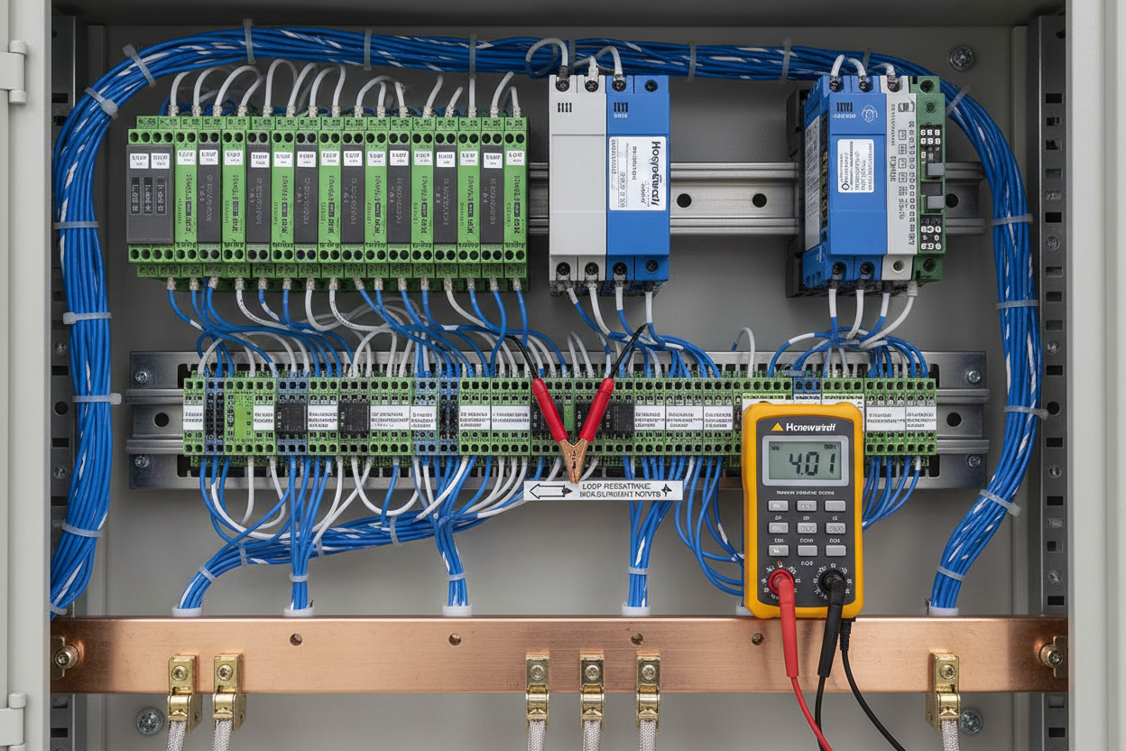
- Loop resistance excess: Total loop resistance above 600 Ω for a 24 VDC source causes the transmitter to under-drive. Measure resistance at the terminal strip with loop de-energized. Target: 250–500 Ω for HART-capable loops.
- Ground loop and common-mode noise: The AXL F AI8 I is galvanically isolated per channel (500 VDC). If noise persists, inspect cable shield grounding. Shield must terminate at one end only — typically the cabinet end on the protective earth bar.
Six-Step Field Fault Isolation Procedure
- Step 1: Confirm power supply voltage at the field terminal block. For a 24 VDC loop with one HART transmitter and the AXL F AI8 I load of 25 Ω, minimum supply voltage is: V_min = (0.020 A × R_total) + V_transmitter_drop. Typical V_min = 10.5 VDC at the transmitter terminals.
- Step 2: Clamp a calibrator (Fluke 789 or equivalent) in series at the transmitter terminals. Force 4.000 mA and read the raw count on the AXL F AI8 I process image via the Axioline F diagnostic interface. Expected: 0 counts ± 5 counts.
- Step 3: Force 20.000 mA. Expected raw count: 32767 ± 50. A reading below 32500 indicates excessive loop resistance or power supply sag.
- Step 4: Force 3.600 mA and confirm the HC900 BROKEN_WIRE flag activates within 200 ms. If not, check the HC900 AI card WIRE_BREAK_EN parameter in the HC900 Designer configuration block.
- Step 5: Inject 12.000 mA (midscale). The HC900 scaled value should read 50.0% ±0.05%. If deviation exceeds 0.1%, recalculate the HC900 scaling constants: EU_at_4mA and EU_at_20mA fields in the Analog Input Function Block parameters.
- Step 6: Restore normal operation. Monitor the DIAG_STATUS word in the AXL F AI8 I for 15 minutes. Any transient DIAG bit activation indicates an intermittent cable fault — inspect field connector crimps and cable routing through conduit bends.
HART Integration and Isolation Monitor Considerations
Many Phoenix Contact AXL F AI8 I installations integrate HART via the AXL F HART module. The loop resistance must be between 230 Ω and 600 Ω for reliable HART communication. The Honeywell HC900 supports HART pass-through on its HAIS (HART Analog Input Smart) cards but not on the standard AI card. Engineers sometimes connect HART-capable transmitters to standard AI cards and wonder why Device Variable Command 3 returns no response — this is by design.
When installing isolation monitoring on safety-instrumented loops, note that IMD (Insulation Monitoring Device) injection current at 1–10 µA can appear as a 0.001–0.01 mA offset on sensitive transmitters. Verify the IMD frequency does not alias into the HART FSK band (1200–2200 Hz). Use a spectrum analyzer or a HART modem in monitor mode to confirm spectral cleanliness before final commissioning.
Scaling Formula Reference
For a 0–100 bar transmitter on the AXL F AI8 I:
EU = (Raw_count / 32767) × 100.0 bar
For the Honeywell HC900 Function Block:
EU = EU_at_4mA + [(mA_input − 4.0) / 16.0] × (EU_at_20mA − EU_at_4mA)
A common error is setting EU_at_4mA to a non-zero value for a zero-based range. Always set EU_at_4mA = 0 and EU_at_20mA = full-scale engineering value for standard linear transmitters. Recheck scaling after any firmware upgrade to the HC900 controller — upgrades can reset function block defaults.
Conclusion and Action Advice
Analog I/O faults in Phoenix Contact AXL F AI8 I and Honeywell HC900 systems follow predictable patterns. First, verify loop power and resistance. Second, inject calibrated test currents to isolate scaling from wiring faults. Third, validate HART capability before assuming pass-through support. Apply the 6-step procedure at commissioning — not only at failure. This produces baseline data that cuts future fault-finding time by 60% in most field cases.
Document every measured raw count, loop resistance, and scaling constant in the instrument data sheet alongside the transmitter data plate. Schedule annual loop calibration checks with a process calibrator capable of 0.025% accuracy to maintain measurement traceability in safety-critical applications.
Author: Zheng Haoyu is an industrial automation engineer with over 10 years of experience in PLC, DCS, and control systems.


