

HART Loop Diagnostics on Emerson and Yokogawa Transmitters: A Field Step-by-Step Guide
The Problem Behind a "Good" Loop
Many technicians trust the milliamp reading alone. That habit causes long outages. A HART loop carries two signals at once. The analog current reports the process value. The digital FSK signal carries diagnostics, ranges and device status. First, remember that these two layers fail independently. Therefore a loop can read 12.00 mA and still refuse to talk.
HART uses Bell 202 frequency shift keying. The carrier sits at 1200 bps. A logic 1 equals 1200 Hz. A logic 0 equals 2200 Hz. The modulated amplitude is only about 1 mA peak-to-peak. That small signal dies quickly in noisy plants.
Physical Layer Numbers You Must Verify
Second, confirm the electrical envelope before touching configuration. Field data beats guesswork every time.
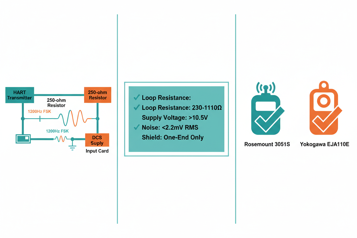
Step 1: Measure total loop resistance. Keep it between 230 and 1100 ohms. Most plants use a 250-ohm precision resistor.
Step 2: Confirm supply voltage at the transmitter terminals. A Rosemount 3051S needs roughly 10.5 V DC minimum at 20 mA.
Step 3: Check cable capacitance. Long runs above 1500 m with high-capacitance cable attenuate the 2200 Hz tone.
Step 4: Measure AC noise across the resistor. Keep broadband noise below about 2.2 mV RMS in the HART extended band.
Step 5: Verify the shield lands at one end only. Double-ended shields create ground loops and phantom retries.
Moreover, log every value on the loop sheet. Auditors and future shifts need that evidence.
Case One: Emerson Rosemount 3051S Drifting in AMS
A refinery reported random bad-quality flags on a 3051S pressure transmitter. The DCS analog value looked stable. However, Emerson AMS Device Manager lost the device several times per shift.
The crew followed a simple sequence. First, they polled the device at address 0 with a 475 communicator. Second, they read the HART 7 device variables and the extended device status byte. Third, they found a high retry count and a "more status available" flag. Fourth, they checked burst mode — a previous engineer had enabled burst at a 0.5 second period.
Burst traffic collided with AMS scanning. Therefore the master saw timeouts. The team disabled burst mode and set the scan interval to 30 seconds. Communication stabilised within one shift. Finally, they documented the change in the loop folder.
Case Two: Yokogawa EJA110E With Intermittent Communication
A boiler feedwater loop used a Yokogawa EJA110E differential pressure transmitter. The signal wandered by 0.3 mA during pump starts. HART polling failed at the same moments.
The engineers traced the cause to cable routing. The instrument tray ran parallel to a 400 V VFD feeder for 60 m. Common-mode noise entered the twisted pair.
Step 1: They separated the trays by 300 mm.
Step 2: They replaced the shield gland with a proper 360-degree termination.
Step 3: They added a HART filter at the DCS input card.
Noise dropped from 6 mV RMS to under 1 mV RMS. The loop then held communication during every pump start. However, remember that filters treat symptoms. Correct routing solves the root cause.
Multidrop and Addressing Traps
Multidrop mode fixes current at 4 mA. Devices then share one pair. Addresses run from 1 to 15 in HART 5 and up to 63 in HART 6 and 7. Two devices at the same address kill the segment. Therefore always scan the full address range before declaring a failure. A silent loop often hides a duplicate polling address.
Conclusion & Action Advice
HART faults follow patterns. Start at the physical layer. Verify resistance, voltage, noise and shielding first. Then inspect masters, burst settings and addresses. Emerson and Yokogawa devices both expose rich diagnostics, so read the extended status byte instead of guessing. Finally, build a one-page loop health checklist and use it on every call. That habit turns a four-hour hunt into a twenty-minute fix.
Author: Zhang Weiming is an industrial automation engineer with over 10 years of experience in PLC, DCS, and control systems.


