

Differential Pressure Transmitter Commissioning for Boiler Drum Level Measurement
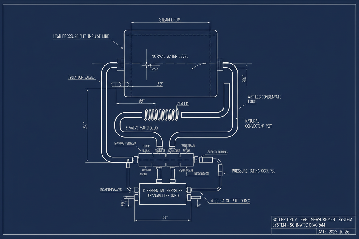
Wet leg configuration, zero suppression calculation, condensate pot design, and HART calibration steps for steam boiler drum level measurement systems
Why Boiler Drum Level Measurement Is Challenging
Boiler drum level measurement is among the most safety-critical measurements in a power plant or refinery. An incorrect level reading leads to low-water shutdown trips, turbine damage from carryover, or catastrophic vessel overpressure if feedwater control fails. Unlike atmospheric tank level applications, boiler drum level measurement operates at pressures of 60–180 bar and temperatures of 270–360°C. These conditions make direct float or displacer level instruments unreliable. Differential pressure transmitters remain the preferred solution because they measure the hydrostatic head difference between the drum high-pressure side and a reference leg filled with condensed water.
Emerson Rosemount 3051 transmitters are widely specified for this service in North American and Asian plants. Honeywell DCS Experion systems integrate these transmitters via HART multiplexers, enabling remote configuration and continuous loop diagnostics. However, errors in wet leg sizing, condensate pot installation, or zero suppression entry produce systematic level errors that the Honeywell DCS controller cannot distinguish from true process changes — until the drum boils dry or overfills.
Understanding the Wet Leg Configuration
A DP transmitter measures boiler drum level by comparing the pressure at the drum bottom with the pressure at the top of a fully flooded reference column called the wet leg. The wet leg connects the high-pressure (HP) side of the transmitter to the steam space at the top of the drum. The low-pressure (LP) side of the transmitter connects to the drum bottom connection, sensing the weight of the drum water column.
The wet leg must remain completely full of water at the condensate temperature throughout all operating conditions. An incompletely filled wet leg introduces a variable reference pressure that mimics false level changes. Engineers install a condensate pot at the top of the wet leg to maintain a constant overflow point regardless of steam condensation rate. The condensate pot overflow level defines the zero reference elevation for all level calculations.
For a boiler drum at 100 bar operating pressure, the condensate in the wet leg is at approximately 50–80°C ambient temperature. Its density is approximately 970 kg/m³. The drum water at 310°C process temperature has a density of approximately 690 kg/m³. This density difference is critical: if the wet leg condensate temperature rises above design due to poor thermal insulation, the wet leg density decreases and the reference pressure drops, which reads as a false increase in drum level.
Therefore, insulate the instrument tubing connecting the drum bottom tapping to the LP transmitter inlet, but do not insulate the wet leg. Allowing the wet leg to remain at ambient temperature maintains maximum condensate density and minimizes density variation errors.
Zero Suppression and Span Calculation
The DP transmitter output does not directly represent level. The wet leg static head creates a constant pressure offset on the HP side. This offset must be suppressed from the transmitter range during commissioning.
In a typical installation, the condensate pot overflow sits 3.5 m above the transmitter centerline. The drum bottom tapping sits 0.3 m above the transmitter. The measurement span covers 0–1.5 m of drum water level. Using condensate density of 970 kg/m³ and drum water density of 690 kg/m³ at operating temperature, the calculated HP minus LP pressure at zero drum level is approximately 31.3 kPa, and at full level it is approximately 21.2 kPa.
Set the Rosemount 3051 LRV to 21.2 kPa (100% level) and URV to 31.3 kPa (0% level). As drum level rises, measured DP decreases — this reverse-acting configuration requires negative span mode via HART command 35. Always use actual fluid densities at operating temperature, not room-temperature water density, to avoid systematic bias.
Step-by-Step Commissioning Procedure
Step 1: Isolate the transmitter and apply 24 VDC loop power. Confirm HART communication using a Rosemount 375 communicator or AMS Device Manager. Verify that no active fault codes are present before proceeding.
Step 2: Set damping to 1.0–2.0 seconds. Boiler drum level signals carry high noise from turbulent boiling. Insufficient damping transmits noise into the feedwater control loop and causes control hunting.
Step 3: Confirm LRV and URV in HART Sensor Trim match the zero suppression calculation. Enter corrected values if any discrepancy exists.
Step 4: Fill the wet leg by opening the condensate pot fill valve. Verify overflow is active — condensate drips from the overflow nozzle — before closing. An incompletely filled condensate pot leaves an air pocket that causes reading drift over hours.
Step 5: Open the manifold equalization valve and zero-trim the transmitter. With the equalization valve open, both HP and LP sides see the same pressure. The output should read the suppressed zero at 100% drum level. If offset exceeds 0.5% of span, apply a zero trim correction via HART and record the trim value.
Step 6: Close the equalization valve and observe the live drum level reading. Cross-check against the drum sight glass. Acceptable deviation is less than 25 mm during stable operation. During startup transients, shrink-and-swell effects cause temporary discrepancies — this is a process phenomenon, not a transmitter error.
Conclusion and Action Advice
Boiler drum level measurement using DP transmitters demands rigorous attention to wet leg design, density compensation, and zero suppression calculation. Keep the wet leg at ambient temperature to maximize condensate density stability. Calculate LRV and URV using actual fluid densities at operating temperature, not room-temperature water density. Always fill the condensate pot to overflow before commissioning to eliminate air pocket errors. After commissioning, cross-verify against the sight glass and configure Honeywell DCS AI scaling to match transmitter engineering units exactly. For safety-critical applications, implement dual transmitter 2oo2 voting logic in the Honeywell Safety Manager to provide independent level protection. These practices prevent the leading cause of boiler drum level measurement failure: a transmitter that is technically functional but systematically reading wrong.


