

Conveyor Safety Interlock Logic: Bachmann M1 and Phoenix Contact PSR-SCP
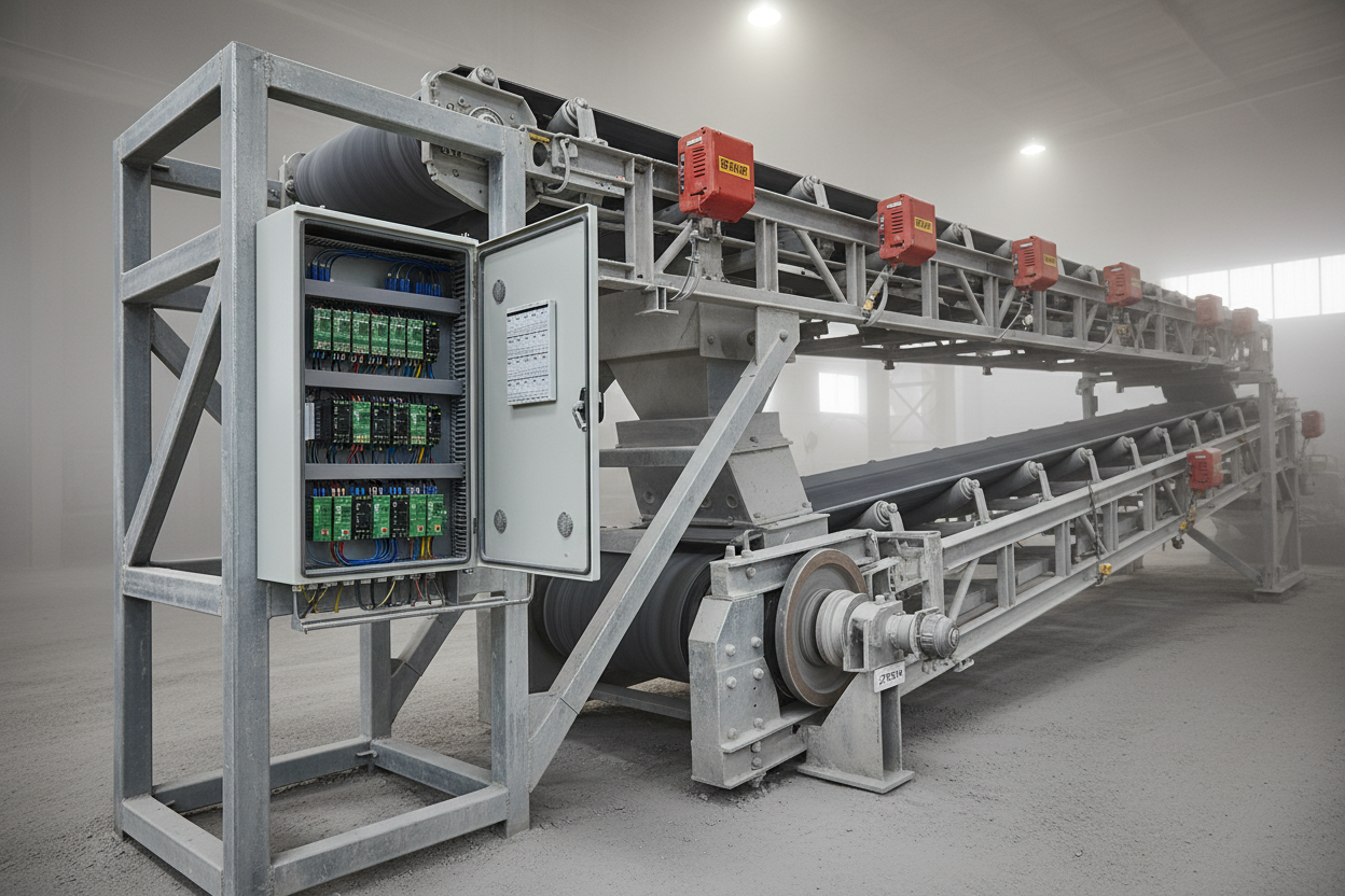
Zone-Based Pull-Cord Shutdown Logic
A three-belt conveyor train requires zone-based shutdown. Belt 3 (discharge end) must reach full speed before Belt 2 starts, and Belt 2 must be running before Belt 1 (intake end) starts — this prevents material pile-up at transfer chutes. The shutdown sequence reverses: Belt 1 stops first and Belts 2 and 3 run for a timed clearance period of 30–60 seconds before stopping.
Pull-cord activations follow an asymmetric zone response. A pull-cord on Belt 3 stops all three belts. A pull-cord on Belt 2 stops Belts 1 and 2 but allows Belt 3 to continue clearing. A pull-cord on Belt 1 stops Belt 1 only. Implement this as a zone matrix in the Bachmann M1 structured text block. A global E-stop approach cannot satisfy ISO 13850 clause 5.4.3 for conveyors operating in separate material handling zones.
After any pull-cord activation, a hardware latch requires physical switch reset at the field location AND a local panel RESET pushbutton press before restart is permitted. HMI remote reset is not allowed per ISO 13850 clause 5.5.2. For applications requiring a dual-channel safety relay architecture, the Allen-Bradley Guardmaster 440R-D22R2 dual input safety relay provides equivalent SIL 2 / PLd performance to the Phoenix Contact PSR-SCP.
Phoenix Contact PSR-SCP Safety Relay Wiring
The Phoenix Contact PSR-SCP is rated SIL 2 / PLd per IEC 62061 and ISO 13849-1. Use one module per belt. It monitors the pull-cord switch chain (Channel A) and E-stop pushbutton (Channel B) simultaneously. Wire OSSD1 and OSSD2 in series to the belt drive contactor coil — this creates a Category 3 stop function with two independent output paths.
Wire Channel A following Phoenix Contact application note AN-PHX-0034 Circuit 1. Connect pin A1 to +24 VDC and wire the pull-cord switch series chain from A1 through all NC contacts to pin S11. Connect S12 to S21. Wire the E-stop NC contact from S22. Connect the PSR-SCP feedback monitoring terminals Y1–Y2 to the belt drive contactor auxiliary NC contact. This feedback detects a welded contactor contact and blocks restart within 300 ms of safety output opening.
Set the PSR-SCP TIME potentiometer to 2 seconds start delay. This prevents immediate restart after a momentary pull-cord release. The Guardmaster GSR delayed output expansion module provides equivalent configurable start delay functionality for Allen-Bradley safety relay architectures. Record the delay value in the safety file as part of the IEC 62061 SIL verification documentation.
Zero-Speed Monitor and Commissioning Tests
Mount a PNP proximity sensor (12–24 VDC, M12 connector) on the tail pulley bracket targeting a 6-slot pulse disk. At full belt speed (1.5 m/s typical), the sensor produces approximately 9–12 Hz. Select a zero-speed monitor relay covering this frequency range — the Pilz PNOZ 13 (0.1–25 Hz) is suitable. Set the relay trip delay to 3 seconds to cover the normal deceleration period during planned shutdowns.
In the Bachmann M1, map the zero-speed relay output to a dedicated DI input. Monitor this input only when BELT_RUN = TRUE AND a 5-second run timer has elapsed — the guard covers the acceleration period. Zero-speed detected after 5 seconds triggers a BELT_SLIP alarm and controlled shutdown. Zero-speed is a diagnostic function, not a safety function — the PSR-SCP handles the safety stop. Document this distinction in the functional specification to avoid compliance ambiguity.
- Step 1: Activate each pull-cord individually. Verify the zone matrix stops the correct belts within 500 ms. Confirm downstream belts continue running.
- Step 2: Verify latch reset. After pull-cord activation, attempt HMI restart — must be rejected. Reset the pull-cord switch, attempt HMI restart again — must still be rejected. Press the local RESET pushbutton — only then should restart be accepted.
- Step 3: Inject an open-circuit on PSR-SCP Channel A (disconnect pin S11). Confirm module drops OSSD outputs, belt stops, and Bachmann M1 generates a SAFETY_RELAY_FAULT alarm with the correct belt number. The Allen-Bradley MSR320P safety relay provides equivalent dual-channel fault detection for comparative testing.
- Step 4: Test zero-speed monitor. Command belt to run, block the tail pulley sensor target. Verify BELT_SLIP alarm within 8 seconds (3 s relay delay + 5 s guard) and controlled shutdown initiates.
- Step 5: Verify sequential start interlock. Attempt to start Belt 1 before Belt 3 is running — confirm rejection with HMI interlock message. Start in correct sequence (Belt 3 → Belt 2 → Belt 1) and confirm all three start with programmed timer delays.
Conclusion and Action Advice
Conveyor safety logic requires precise architecture from the design stage. First, implement zone-based pull-cord shutdown logic in the Bachmann M1 structured text block — a global E-stop cannot satisfy zone-specific material clearance requirements. Second, use Phoenix Contact PSR-SCP (or equivalent Allen-Bradley Guardmaster safety relay) with dual-channel wiring and contactor feedback loop to achieve the SIL 2 / PLd architecture.
Set the PSR-SCP start delay to 2 seconds and document this value in the SIL verification file. Run all five fault injection tests before operational handover — do not skip the PSR-SCP open-circuit test, as this is the only way to confirm dual-channel monitoring is active. Set the zero-speed relay trip delay to 3 seconds and apply the 5-second PLC guard timer to prevent nuisance trips during planned belt shutdowns. The Guardmaster expansion module enables scalable safety relay architectures as conveyor systems grow.
Author: Shen Weicheng is an industrial automation engineer with over 10 years of experience in PLC, DCS, and control systems.


