Triple-Redundant Flow Measurement: 1 Orifice Plate, 3 DP Transmitters — ABB and Bently Nevada Implementation
Why One Transmitter Is Never Enough in a Safety-Critical Line
A single differential pressure transmitter on a gas compressor discharge line costs roughly $1,200. A compressor trip caused by a spurious high-flow signal costs $85,000 per hour in lost production. A single DP transmitter cannot tell you whether its reading is wrong — it just reports a number. You have no way to know if a blocked impulse line, a failed diaphragm, or a firmware fault corrupted the output. For SIL-rated loops and critical process flows, you need three transmitters measuring the same orifice plate differential. Three signals let a 2-out-of-3 (2oo3) or 1-out-of-3 (1oo3) voting logic detect and isolate a faulty transmitter without shutting down the process. This design also meets IEC 61511 requirements for Safety Instrumented Functions at SIL 2 level.
ABB 266 series transmitters handle the high-accuracy measurement role. Bently Nevada, traditionally known for vibration monitoring in turbomachinery, also produces process transmitters suited for compressor and turbine lines where shaft vibration data and process flow data feed the same control system. Combining both brands on one orifice plate maximizes diagnostic depth.
Mechanical Design — Orifice Plate and Impulse Lines
Use a concentric square-edge orifice plate per ISO 5167-2. Select a beta ratio (d/D) between 0.3 and 0.75 for best accuracy. At a beta of 0.6 with 150 mm pipe bore, maximum differential pressure at full flow reaches 250 mbar. All three transmitters tap from the same upstream and downstream pressure taps. Use flanged taps or D-and-D/2 taps — corner taps are acceptable for pipe bores under 50 mm.
- Install the orifice flange assembly with the upstream straight-run length of 20× pipe diameter to avoid swirl. Downstream straight-run minimum is 5× pipe diameter before the next fitting.
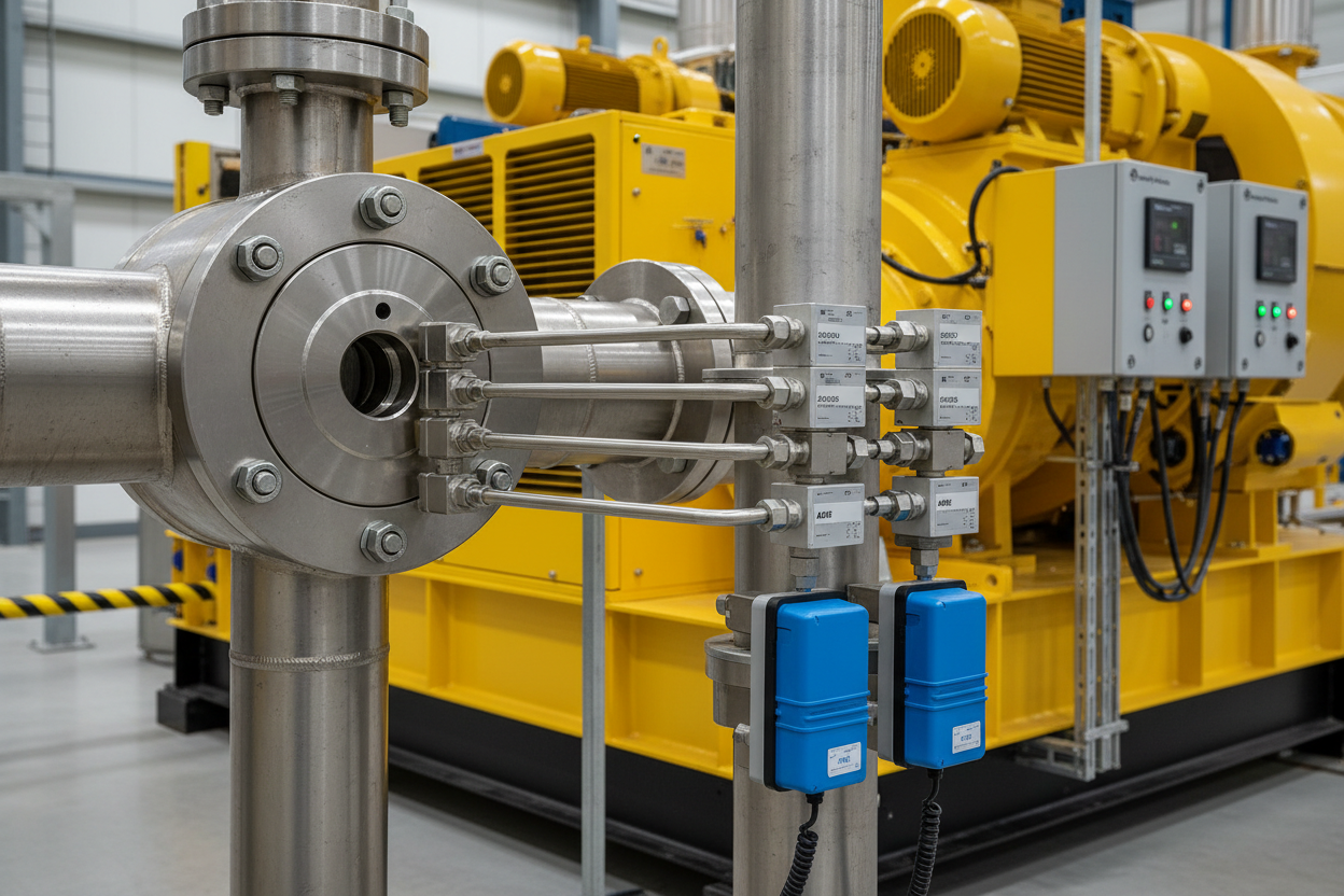
- Route three independent impulse tube sets — 12 mm OD stainless steel — from the same tap pair to each transmitter. Do not share a common manifold before the transmitter; shared manifolds propagate single-point failures.
- Slope all liquid-service impulse lines downward to drain at 1:12 minimum gradient. For gas service, slope upward so condensate drains back to the pipe. Incorrect slope traps liquid or gas pockets and shifts zero by up to 15 mbar.
- Install individual 3-valve manifolds at each transmitter. This allows one transmitter to equalize and isolate for calibration while the other two remain in service.
Transmitter Configuration — ABB 266DSH and Bently Nevada DP
ABB 266DSH spans a differential pressure range of 0–250 mbar for this application. Set damping to 0.5 seconds — fast enough for control, slow enough to reject impulse-line noise. Configure the output to transmit in HART protocol on a 4-20 mA loop. Use ABB HART Device Type Manager (DTM) in FieldCare to set URL = 4 mA at 0 mbar, URV = 20 mA at 250 mbar. Set process fluid density in the transmitter for square-root extraction if the DCS does not perform this calculation.
Bently Nevada process transmitters use the same 4-20 mA HART interface. Assign each of the three transmitters a unique HART address (address 0 for point-to-point mode). Long multidrop HART loops with address conflicts are a common field error — always confirm address uniqueness with a HART communicator before commissioning.
- Connect each transmitter to a dedicated DCS analog input card. Do not multiplex three transmitter signals through a single HART multiplexer for SIL-rated loops — card-level isolation is mandatory.
- Configure the DCS (for example, Emerson DeltaV or ABB System 800xA) to apply square-root extraction and EU scaling on each of the three raw 4-20 mA signals independently. Output unit: standard cubic meters per hour (Sm³/h).
- Set each AI card input range to 3.8–20.5 mA to detect open-loop (below 3.8 mA) and saturated-high (above 20.5 mA) faults. Both conditions trigger transmitter fault alarms immediately.
Voting Logic — 2oo3 Signal Selection in DCS
2-out-of-3 voting selects the median of the three flow signals. When all three agree within a deviation band of ±5 % of span, the median is the process value. When one transmitter deviates beyond 5 % from the median, the logic flags it as suspect, generates an alert, and continues to use the median of the remaining two. A fault in a second transmitter triggers a safety action — trip or override — because only one reliable signal remains.
- Configure the deviation band in the DCS function block as an engineering-unit value (e.g., 12.5 Sm³/h at a 250 Sm³/h span).
- Avoid a percentage-of-reading band; it collapses near zero flow and causes false deviations during low-load periods.
- Build the 2oo3 median selector using the DCS's built-in MED3 or equivalent function block. Wire all three EU-scaled flow signals to the block inputs.
- Add three deviation comparators — one per input versus the median output. Set deviation limit = 12.5 Sm³/h (5 % of 250 Sm³/h span).
- Route deviation alarm bits to the alarm management system with priority High. Label alarms: FT-101A DEVIATION, FT-101B DEVIATION, FT-101C DEVIATION.
- Test the logic during commissioning by injecting 4 mA into one transmitter channel and confirming the median selects the average of the other two while generating the deviation alarm.
Maintenance and Calibration Without Process Shutdown
The 3-valve manifold at each transmitter allows in-service calibration. One transmitter at a time steps out of service — equalize the manifold, isolate high and low pressure ports, connect a precision dead-weight tester or reference pressure source. Apply 0, 25, 50, 75, and 100 % of span. ABB 266DSH accuracy specification is ±0.04 % of reading — verify trim if any point drifts beyond ±0.1 %. HART diagnostic variables to check during every calibration: sensor temperature (must stay within –40 to 85 °C), sensor capacitance (drift beyond 5 pF indicates diaphragm damage), and loop current (compare against DCS reading to detect wiring resistance errors).
Blocked impulse lines are the number-one failure mode on outdoor installations. Inspect and blow-down impulse lines quarterly in liquid service. Use the difference between three transmitter readings as a diagnostic: a single transmitter reading low by 15–30 mbar while the other two agree indicates a partial impulse-line blockage on the high-pressure port of that transmitter. Replace or flush the impulse line before returning the transmitter to service.
Engineering Recommendations
Specify triple-redundant DP transmitters on any orifice flow loop that feeds a SIL-rated safety function or a compressor anti-surge control loop. Use ABB 266DSH for the primary measurement channel — its ±0.04 % accuracy and HART diagnostics are well-proven on gas service. Add two Bently Nevada DP transmitters for the redundant channels, especially when the transmitters share a rack with the turbine protection system and data integration simplifies the architecture. Always route impulse lines independently from the orifice taps to each transmitter. Never share piping between two transmitters of a redundant set. Configure the DCS 2oo3 median block with a fixed EU deviation band, not a percentage band. Schedule impulse-line inspections quarterly and individual transmitter calibrations annually. An investment of three transmitters instead of one adds roughly $2,400 to the project cost and avoids the $85,000-per-hour exposure from a spurious shutdown. For flow measurement on compressor lines, also consider the ABB FSM4000 electromagnetic flowmeter as a cross-check instrument on liquid-phase streams.


