

- CIP Class 1 implicit messaging RPI, ControlLogix 5580 VFD integration, DLR Device Level Ring PowerFlex 525, F81 Comm Loss fault diagnosis, multi-drive EtherNet/IP performance tuning, PowerFlex 525 EtherNet/IP commissioning, PowerFlex 525 Logic Command Status word, Studio 5000 Add-On Profile AOP version
Commissioning Allen-Bradley PowerFlex 525 VFDs on ControlLogix 5580 Over EtherNet/IP: A Complete Field Guide
Q: Why Does PowerFlex 525 EtherNet/IP Integration Require Precision Setup?
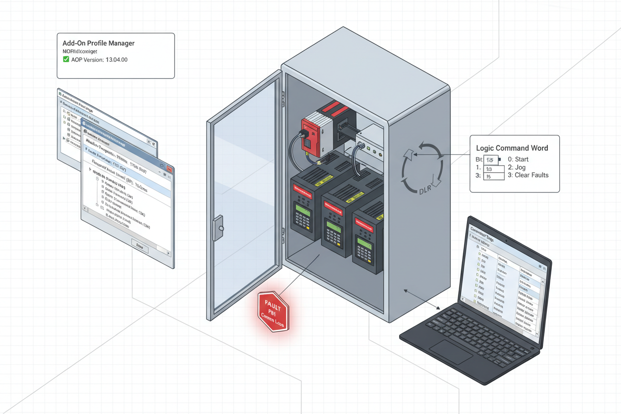
PowerFlex 525 drives communicate over EtherNet/IP using the Common Industrial Protocol (CIP). The Allen-Bradley 1756-L83E ControlLogix 5580 Controller establishes a Class 1 CIP connection for cyclic I/O data — speed reference, speed feedback, status word, and command word. Three factors cause most commissioning failures: the Add-On Profile (AOP) version must match the drive firmware, the RPI must align with the application’s speed control requirements, and the drive IP address must exactly match the Studio 5000 module configuration. The Allen-Bradley 1756-EN2T EtherNet/IP Communication Bridge Module provides the EtherNet/IP scanner port in the ControlLogix chassis for PowerFlex 525 drive connections.
Q: How Do I Install the Correct AOP and Configure the Drive IP?
- Step 1 — Install AOP: In Studio 5000, go to Tools → Add-On Profile Manager. Verify the PowerFlex 525 AOP version matches your drive firmware. For firmware v7.001, install AOP v4.01 or later. Download from Rockwell PCDC. Install with Studio 5000 closed, then restart.
- Step 2 — Configure Drive IP: Power on the PowerFlex 525. On the HIM keypad, navigate to parameter C128 (IP Address Configuration). Set C128 = 1 (Static IP). Enter parameters C129–C132 for IP address octets, C133–C136 for subnet mask, C137–C140 for gateway. Typical: IP 192.168.1.25, Subnet 255.255.255.0, Gateway 192.168.1.1. Cycle power after setting. Verify with a ping from the engineering workstation.
Q: How Do I Add the Drive to Studio 5000 and Configure the Connection?
- Step 3 — Add Module: Right-click the Ethernet port on the 5580 controller → New Module. Search for “PowerFlex 525-EENET” and select the exact catalog number. Set Module Name (e.g., PF525_Pump_01) and IP address matching Step 2.
- Step 4 — Configure Connection: On the Connection tab, set RPI = 10.0 ms for general-purpose applications, 5.0 ms for speed-critical loops, 2–5 ms for positioning. Set Input Size = 4 words (default) or 8 words (extended). Set Output Size = 4 words. Check “Use Unicast Connection” for point-to-point topologies.
-
Step 5 — Map Tags: Studio 5000 auto-creates tags:
PF525_Pump_01:I.Data[0](Logic Status),PF525_Pump_01:I.Data[1](Speed Feedback Hz×10),PF525_Pump_01:O.Data[0](Logic Command),PF525_Pump_01:O.Data[1](Speed Reference Hz×10). Logic Command bit map: Bit 0 = Stop, Bit 1 = Start, Bit 2 = Jog, Bit 3 = Clear Faults, Bit 7 = Forward/Reverse. Logic Status: Bit 0 = Ready, Bit 1 = Active, Bit 7 = Faulted, Bit 8 = At Reference.
Q: How Do I Access Drive Parameters via Explicit Messaging?
For parameters not covered by the I/O assembly, use MSG instructions with Message Type = CIP Generic, Service Type = Get Attribute Single (read) or Set Attribute Single (write), Class = 0x0f, Instance = parameter number, Attribute = 0. For example, to read P041 (Accel Time 1): Instance = 41, Service = Get Attribute Single. Execute the MSG on a 1-second periodic timer — never every scan, as this overloads the EtherNet/IP connection.
Q: How Do I Diagnose the Three Most Common PowerFlex 525 EtherNet/IP Faults?
- Fault F81 — Comm Loss: The 5580 lost the CIP Class 1 connection. Check Ethernet cable continuity first. Increase RPI from 2 ms to 10 ms as a diagnostic step. Verify parameter C129 IP address matches Module Properties exactly — a single octet mismatch causes this fault.
- Error 16#0204 — Connection Request Timeout: The drive is not responding to CIP connection requests. Verify the drive is not already connected to another controller — PowerFlex 525 supports only 2 simultaneous Class 1 connections. Use Studio 5000 Who Active tool to identify other controllers with active connections.
- Fault F100 — Parameter Out of Range: A MSG instruction wrote a value outside parameter limits. Check P034 (Minimum Frequency) and P035 (Maximum Frequency) before writing speed references.
Q: How Do I Tune EtherNet/IP Performance for Multi-Drive Networks?
For more than five PowerFlex 525 drives on a single ControlLogix 5580, set RPI by criticality: critical process drives 5 ms, auxiliary drives 20 ms, non-critical drives 50 ms. Enable CIP Sync (IEEE 1588 PTP) if drives support it (firmware v5.001+) for sub-microsecond clock synchronization. Monitor the 5580 Ethernet module Port Diagnostics — Percent Utilization must stay below 60%. Above 80%, add a second Ethernet module or move non-critical drives to a separate VLAN. Implement a heartbeat counter between the 5580 and each drive: if the counter fails to increment for 3 consecutive RPI periods, trigger a Comm Loss alarm.
What Is the Key Action Advice?
Match the AOP version to the drive firmware first — this single step prevents hours of troubleshooting. Configure RPI appropriate for each drive’s process criticality, not a uniform default. Use Logic Command and Status word bit-level diagnostics in ladder logic to automatically detect and annunciate drive faults. Test the complete drive start-stop sequence with the output contactor open (no motor connected) before commissioning with the load — this catches 90% of configuration errors without risking equipment. Document every drive’s IP address, RPI setting, and parameter backup in Studio 5000 Project Documentation before handover to operations.
Author: Zhang Hongwei is an industrial automation engineer with over 10 years of experience in PLC, DCS, and control systems, specializing in Allen-Bradley ControlLogix and PowerFlex drive systems, EtherNet/IP network design, and Studio 5000 programming.


