

Thermocouple Wiring, Standards, and Troubleshooting: A Practical Field Guide
Understanding Thermocouple Operating Principles
A thermocouple generates an electromotive force (EMF) when two dissimilar metal wires join at a hot junction and a cold junction. The Seebeck effect drives this voltage, which varies predictably with temperature difference between the two junctions. However, accurate measurement requires more than inserting a probe into a process. Engineers must select the correct thermocouple type, wire the circuit with matched extension wire, and compensate for cold junction temperature variation. The Yokogawa AMM32TJ RTS Input Multiplexer Module provides multi-point thermocouple and RTD signal acquisition for Yokogawa CENTUM DCS systems, while the Yokogawa AMM12 Voltage Input Multiplexer Module handles millivolt-range thermocouple signals in high-density temperature measurement applications.
IEC 60584 Thermocouple Type Codes and Application Ranges
IEC 60584 defines standard thermocouple types, their alloy compositions, and tolerance classes. Selecting the wrong type introduces systematic error that calibration cannot correct.
- Type K (Chromel–Alumel): −200°C to +1260°C, ~41 µV/°C at 500°C. Suits most general industrial applications. Exhibits a Curie point anomaly near 180°C causing brief non-linearity.
- Type J (Iron–Constantan): −40°C to +750°C, 51 µV/°C. Suits reducing atmospheres but oxidizes rapidly above 500°C in air. Use only in sealed or purged assemblies at elevated temperatures.
- Type T (Copper–Constantan): −200°C to +350°C. Excellent stability in moist or cryogenic environments.
- Type R and S (Platinum–Rhodium alloys): Up to 1600°C for kilns and heat treatment. Low output of 6–10 µV/°C requires high-impedance, low-noise amplifiers.
IEC 60584 Class 1 tolerance for Type K is ±1.5°C from −40°C to +375°C, and ±0.4% of reading above 375°C. Class 2 doubles these tolerances. Specify the tolerance class in the instrument datasheet at the engineering stage.
Extension Wire and Compensating Cable Selection
The most common wiring mistake in thermocouple circuits is substituting standard copper cable for thermocouple extension wire. Copper conductors introduce an EMF error at every junction where the material changes from thermocouple alloy to copper. Use extension-grade wire (same alloy composition as the thermocouple) for runs up to 30 meters from the probe to the transmitter or junction box. For longer runs or high-temperature terminal areas, use compensating cable, which uses different but EMF-matched alloys at lower cost.
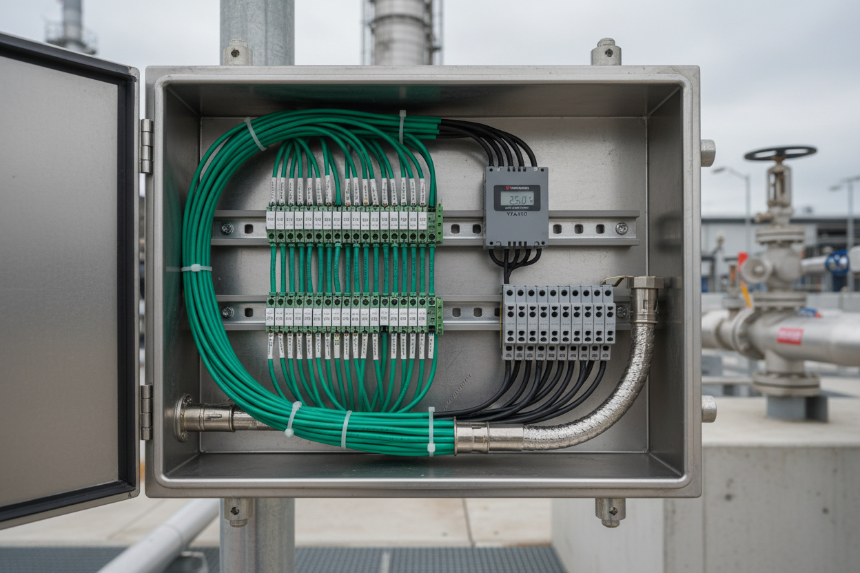
Phoenix Contact WTOP series thermocouple terminal blocks are particularly useful in field junction boxes. They incorporate a precision CJC sensor on each terminal block, measuring the local ambient temperature. Each WTOP block is color-coded per IEC 60584 type: green for Type K, black for Type J, brown for Type T.
- Step 1: Maintain polarity throughout the circuit. Thermocouple extension wire uses color-coded insulation per IEC 60584. Never reverse positive and negative conductors at any junction.
- Step 2: Run thermocouple cables in separate conduit from power cables. Induced EMF from 50 Hz AC raises noise above the microvolt range of noble-metal thermocouples. Connect cable shields at the transmitter end only to prevent ground loops.
- Step 3: Use ceramic or stainless terminal blocks inside the junction box. Tin-plated terminals corrode in humid environments, creating additional thermoelectric junctions that offset readings.
Cold Junction Compensation in Field Transmitters
Every thermocouple measurement references the cold junction temperature. Modern transmitters replace the traditional ice bath with an electronic CJC sensor at the input terminal block. The Yokogawa YTA110 measures terminal block temperature with its internal PT100 CJC sensor, then adds the cold junction voltage equivalent before converting to degrees Celsius using NIST ITS-90 polynomial coefficients in firmware.
CJC errors arise from direct sunlight heating the transmitter housing, nearby steam tracing creating a thermal gradient, or overtightened terminal screws deforming soft extension wire. In critical applications, verify CJC accuracy by immersing the hot junction in an ice bath at 0.00°C. Any residual error indicates a CJC fault or extension wire wiring error.
Systematic Troubleshooting for Thermocouple Loops
- Open circuit: The transmitter outputs its configured upscale burnout current (typically 21.0 mA) or downscale burnout current (3.6 mA). Check for HART diagnostic status “Sensor Failure.” Measure continuity from the probe tip to the transmitter input terminals. A complete open indicates a broken thermocouple wire inside the sheath, a loose terminal screw, or a conduit pull that severed extension wire.
- Short circuit: The transmitter reads ambient temperature regardless of process temperature changes. The thermocouple junction has internally short-circuited inside the protection tube, most commonly due to moisture ingress or mechanical damage. Withdraw the probe and inspect the tip under magnification.
- Calibration drift: Readings are consistently high or low compared to a nearby reference thermometer. Check extension wire polarity throughout the circuit. A single reversed junction introduces a constant offset equal to twice the voltage at that junction temperature. Also inspect for partial short circuits in the sheath, which reduce EMF output without causing complete failure.
Moreover, periodically compare readings from redundant temperature transmitters on the same process. A deviation of 3°C or greater indicates drift. Schedule calibration verification for both instruments and accept the one confirmed against a traceable reference.
Conclusion and Action Advice
Thermocouple accuracy depends on disciplined wiring, correct extension wire selection, and reliable cold junction compensation. Yokogawa YTA series transmitters provide excellent internal CJC accuracy, but cannot compensate for wiring polarity errors or incorrect extension wire types. Phoenix Contact WTOP terminal blocks with integrated CJC sensors reduce installation errors in multi-point junction boxes. Review thermocouple circuits against IEC 60584 at commissioning, verify open-circuit burnout direction matches your safety logic, and include thermocouple checks in your annual calibration schedule.
Author: Chen Liangwei is an industrial automation engineer with over 10 years of experience in PLC, DCS, and control systems.


