

Thermocouple and RTD Signal Integrity: Cable and Grounding
Why Signal Integrity Matters
A Class A Pt100 RTD has a tolerance of ±0.15°C at 0°C. A Type K thermocouple has a tolerance of ±2.2°C at 500°C. These accuracies are meaningless if the signal cable introduces more error. Thermocouple signals are in the millivolt range — a 1°C error corresponds to 40 µV, and induced noise of 200 µV produces a 5°C reading error. The error budget must include the cable. The Honeywell MC-TAIH02 High Level Analog Input Module and the Honeywell CC-PUIO01/C Universal I/O Module accept thermocouple and RTD inputs directly, but neither can detect cable-induced errors — regular loop calibration is the only way to catch them.
Thermocouple Extension Wire Selection
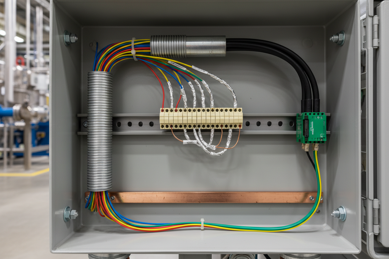
Thermocouple extension wires use alloy conductors that match the thermocouple EMF curve. Using ordinary copper wire defeats the purpose — copper generates parasitic thermocouple junctions at each end, and the error can exceed 20°C. Select the correct insulation: PVC is rated for 105°C maximum, XLPE for 150°C. For higher temperatures, use fiberglass braid or stainless steel overbraid. Choose the correct shield — Phoenix Contact FLK series has a tinned copper braid with 85% coverage. Ground the shield at one point only, typically at the transmitter end. Grounding at both ends creates a ground loop that induces noise in the signal conductors.
RTD Cable Sizing and Wiring
RTD sensors use a 1 mA constant current excitation. Three-wire and four-wire configurations compensate for cable resistance. In a three-wire RTD, the transmitter assumes the two lead wires have the same resistance — this is valid only if all three wires are the same length and gauge.
- Wire resistance: A 0.5 mm² copper wire has 36 milliohms per metre. For 50 metres, the resistance is 1.8 ohms per wire. If one lead is 1.8 ohms and another is 2.0 ohms, the error is 0.1 ohms, or 0.26°C for Pt100. Use the same wire gauge and length for all RTD leads.
- Cable shielding: Select RTD cable with a foil shield plus drain wire. Ground the drain wire at one point. For hazardous areas, use IS-rated cable with a blue jacket. Excessive cable capacitance (>200 nF/km) can cause the IS barrier to oscillate and produce false readings.
Grounding Philosophy
For thermocouple circuits, the negative lead is usually grounded at the transmitter to reduce common-mode noise. However, if the thermocouple sheath is also grounded at the measurement point, a ground loop forms. The solution is an isolated transmitter — Emerson Rosemount 644 with isolation and Honeywell STT3000 with channel-to-channel isolation both break ground loops effectively.
For RTD circuits, ground the shield at the transmitter end only. The RTD element is usually not grounded — grounding the element increases ground loop risk. If the RTD sheath is grounded at the process connection, use an isolated input transmitter. Use a single-point ground busbar in each junction box and connect the busbar to the plant earth grid with a single conductor, not a daisy chain.
Step-by-Step Noise Reduction
- Step 1: Disconnect the sensor and measure open-circuit voltage. For a thermocouple, use a voltmeter with >1 MΩ input impedance. The reading should be stable within ±10 µV. For an RTD, use a four-wire ohmmeter. The reading should be stable within ±0.05 ohms.
- Step 2: Check shield continuity. Measure resistance from the shield drain wire to the ground busbar — it should be less than 1 ohm. Verify the shield is grounded at one point only. Disconnect the shield at the sensor end and measure resistance to ground — it should be infinite.
- Step 3: Measure AC voltage between signal wires and ground. Set the voltmeter to AC millivolt range. Above 10 mV AC indicates electromagnetic interference. Route the signal cable at least 300 mm away from power cables.
- Step 4: Install a signal isolator if ground loops cannot be eliminated. Phoenix Contact MINI Analog Pro provides 3-way isolation with <0.1% error. It breaks all ground loops and provides common-mode noise rejection up to 2 kV.
Troubleshooting False Readings
- Sudden jump to maximum reading: Indicates an open circuit. Check the connection at the sensor head. Vibration loosens screw terminals. Tighten all terminals to the specified torque (typically 0.5 N·m for 1.5 mm² wire).
- Consistent offset: Indicates mismatched thermocouple type. Verify the transmitter configuration. A Type K configured as Type J reads approximately 50°C low at 500°C. An RTD configured as “Cu10” instead of “Pt100” reads 26 times higher than actual temperature.
- Slow response: Indicates poor thermal contact. For a thermowell-mounted RTD, use a spring-loaded element. For a surface-mounted thermocouple, use a sensing pad with high-thermal-conductivity adhesive. A poorly mounted surface thermocouple can have a response time exceeding 10 minutes.
Conclusion and Action Advice
Signal cable selection, grounding, and shielding are as important as sensor selection. Use the correct thermocouple extension wire type. Ground shields at one point only. Use three-wire or four-wire RTD for runs longer than 30 metres. Isolate the transmitter if ground loops cannot be avoided. Keep spare thermocouple extension wire for emergency repairs. Label each cable with the sensor tag number at both ends.
Author: Weijie Huang is an industrial automation engineer with over 10 years of experience in PLC, DCS, and control systems.


