Pressure Relief Valve Sizing, Testing, and Maintenance in Process Plants
Engineering fundamentals and field practices for PRV selection, API 520/526 sizing, set pressure adjustment, and in-situ pop testing procedures
Role and Types of Pressure Relief Valves
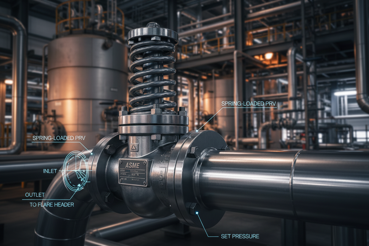
A pressure relief valve (PRV) is a spring-loaded device that automatically opens when upstream pressure exceeds a predetermined set point. It discharges fluid to relieve the overpressure condition, then reseats when pressure drops to the blowdown pressure. PRVs protect pressure vessels, heat exchangers, piping systems, and pumps from exceeding their design pressure limits.
Three types dominate industrial process plants. First, the conventional spring-loaded relief valve is the most common type. The spring force holds the disc against the nozzle seat. When inlet pressure exceeds the set pressure, the disc lifts and flow is discharged to the relief header. This type is sensitive to back pressure in the discharge header — increasing back pressure reduces the effective set pressure and can cause chatter.
Second, the balanced bellows relief valve isolates the spring chamber from the discharge side using a flexible bellows element. This design tolerates variable or superimposed back pressure up to 50% of set pressure without affecting opening performance. It is the preferred choice for corrosive services and situations with significant built-up back pressure.
Third, the pilot-operated relief valve (PORV) uses system pressure to hold the main piston closed. A small pilot valve senses inlet pressure and releases the main piston when the set pressure is reached. PORVs can be set much closer to operating pressure (within 5%) without false opening or simmering. They are widely used in high-pressure and high-capacity gas service where conventional spring-loaded valves would be excessively large.
Sizing Fundamentals per API 520 and ASME Code
Undersized relief valves cannot relieve the design overpressure case quickly enough. Oversized valves chatter — they rapidly open and close repeatedly — which damages the seat and disc and causes premature leakage. Correct sizing is therefore critical for both safety and reliability.
The primary sizing standard for process plants is API Standard 520 (Sizing, Selection, and Installation of Pressure-Relieving Devices). The companion standard, API 526, specifies flange ratings, orifice designations, and standard inlet/outlet sizes.
The basic liquid flow sizing equation determines the required effective discharge area A:
For liquid service: A = Q / (38 × Kd × Kw × Kc × √(ΔP / G))
Where Q is volumetric flow rate (US gal/min), Kd is the effective coefficient of discharge (typically 0.65 for liquid service), Kw is the back-pressure correction factor, Kc is the combination correction factor for rupture disc installation, ΔP is the pressure differential at set conditions (psi), and G is specific gravity relative to water.
For gas and vapor service, the compressibility factor Z and specific heat ratio k enter the equation, and the critical versus subcritical flow regime must be determined before applying the sizing formula.
The ASME Section VIII code allows vessels to be protected at 110% of maximum allowable working pressure (MAWP) for a single relief valve installation, or at 116% for fire case protection with two relief valves. The relief valve set pressure must not exceed the vessel MAWP stamped on the nameplate.
Overpressure cases that must be considered during sizing include: blocked outlet, reflux failure, external fire, tube rupture in heat exchangers, thermal expansion of blocked-in liquids, and utility failure scenarios. The largest required relief area from all credible cases determines the final valve selection.
Emerson’s Anderson Greenwood and Crosby product lines cover the full range of conventional, balanced bellows, and pilot-operated relief valves for API process service. Their online sizing tools implement API 520 equations and generate ASME-compliant documentation packages for pressure vessel registration.
Set Pressure Adjustment and Verification
The set pressure is the inlet gauge pressure at which the relief valve is designed to open. ASME code requires that the actual cold differential test pressure (CDTP) be within ±3% of the nameplate set pressure for set pressures above 70 psig, and within ±2 psi for set pressures at or below 70 psig.
Set pressure adjustment requires removing the valve from service. The valve is bench-tested on a certified test stand against a calibrated pressure source.
Step 1: Cold Differential Correction — If the process operating temperature differs significantly from ambient bench test temperature, apply a temperature correction factor to account for spring rate changes with temperature. The CDTP will differ from the operating set pressure by this correction amount.
Step 2: Spring Adjustment — The set pressure is adjusted by tightening or loosening the adjusting screw on the spring bonnet. Tightening the screw increases spring force and raises the set pressure. Each quarter-turn of the adjusting screw changes set pressure by a manufacturer-specified increment — typically 2–15 psi depending on the spring range.
Step 3: Pop Test — Apply inlet pressure slowly using nitrogen or water. Record the pressure at which the disc lifts and the blowdown pressure at which it reseats. Verify both values are within ASME tolerance. For spring-loaded valves, blowdown is typically 7–10% below set pressure.
Step 4: Seat Leak Test — After reseating, apply 90% of set pressure and confirm no visible leakage at the disc seat for at least one minute. Leakage indicates seat damage or contamination. Lap or replace the seat and disc as required.
Step 5: Tamper Seal and Documentation — Apply a tamper-evident seal across the adjusting screw cap after passing the bench test. Issue a calibration certificate recording the set pressure, test date, technician, test equipment serial numbers, and next due date.
In-Service Inspection and Maintenance Program
API Recommended Practice 576 (Inspection of Pressure-relieving Devices) provides the framework for inspection intervals and acceptance criteria. The risk-based inspection (RBI) methodology from API 580 allows plants to extend or reduce inspection intervals based on corrosion rate, service severity, and historical valve performance.
Conventional inspection intervals for relief valves in general hydrocarbon service are 5 years. Corrosive or fouling services require 2–3 year intervals. Valves in clean utility service such as steam or clean nitrogen may qualify for 10-year intervals under an RBI program with documented engineering justification.
Common Failure Modes Encountered During Inspection:
- Seat leakage — the most common in-service failure. Corrosion, erosion, or process deposits damage the lapped seating surfaces. Minor seat damage can be corrected by hand lapping. Severe damage requires new seat and disc components.
- Spring corrosion and cracking — stress corrosion cracking (SCC) in H2S or corrosive services can cause catastrophic spring failure. Springs must be visually inspected for pitting, corrosion, and cracks. Replace springs showing any visible damage.
- Inlet nozzle fouling — polymerizing fluids, scale, or coke deposits partially block the inlet nozzle, reducing actual relieving capacity below the designed value. Valves in fouling services require shorter inspection intervals and possibly a heat-traced or purge-maintained inlet connection.
- Stuck-open condition — caused by process deposits holding the disc off the seat after a relieving event. A partially open relief valve leaks continuously, wastes product, and fails to provide full protection for the next overpressure event. Always inspect and bench-test after any known relieving event.
GE Oil and Gas (now Baker Hughes) pressure relief valves used in offshore and high-pressure gas applications include duplex stainless steel components specifically designed for hydrogen sulfide (H2S) NACE MR0175-compliant service. When selecting relief valves for sour gas service, verify that all wetted metallic parts meet NACE hardness and material requirements to prevent sulfide stress cracking.
Conclusion and Action Advice
Pressure relief valves protect both personnel and plant assets, but only when correctly sized, properly set, and regularly maintained. Apply API 520 sizing discipline to all overpressure scenarios — do not size for a single case and assume conservatism covers the rest. Establish a documented inspection program per API 576 with RBI justification for extended intervals. Bench-test every valve at its scheduled interval or after any known relieving event. Record cold differential test pressure corrections for every high-temperature installation. Never return a valve to service with seat leakage — even a small continuous leak accelerates seat damage and eventually prevents the valve from reseating after the next overpressure event. A well-maintained PRV program costs a fraction of a single unplanned vessel rupture or process shutdown.


