Mastering Modbus TCP Implementation for Modern Industrial Automation
Modbus TCP remains a cornerstone of factory automation despite being one of the oldest protocols in the industry. Many engineers face a steep learning curve when moving beyond simple digital I/O to protocol-based communication. While Modbus offers high compatibility, its implementation requires a structured approach to hardware addressing and register mapping. This guide breaks down the process of transforming a raw Modbus device into a functional part of your control system.
Comparing Modbus TCP and EtherNet/IP Frameworks
The primary distinction between Modbus and modern protocols like EtherNet/IP lies in data consistency and configuration overhead. Most Ethernet-based protocols require Electronic Data Sheets (EDS) or specific hardware profiles to define data structures. However, Modbus TCP operates without these predefined templates. You do not need to inform the PLC about the byte-count of incoming packets beforehand. Instead, you simply target an IP address and a specific starting register to initiate communication.
Configuring Hardware and Network Parameters
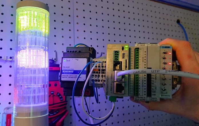
Before writing any PLC logic, you must establish a solid network foundation for your peripheral devices. Using a Patlite LA6-LAN stack light as an example, the process begins with an onboard web server. You must assign the device an IP address within the same subnet as your primary controller. Most industrial automation hardware uses Port 502 as the default for Modbus traffic. Ensuring the "Modbus TCP Enable" flag is active remains a critical, yet often overlooked, initial step.
Decoding Modbus Function Codes and Register Logic
Understanding function codes is the most vital aspect of managing Modbus-enabled control systems. Most manuals categorize data into Coils (Booleans) and Holding Registers (16-bit Integers). For complex devices like multi-color signal towers, manufacturers often utilize registers to handle multiple states. For instance, a single register might control a light’s color, brightness, and flash pattern. You must convert these requirements into decimal or hexadecimal values that the PLC can transmit effectively.
Implementing Modbus Write Commands in AutomationDirect PLCs
AutomationDirect controllers, such as the Productivity series, simplify the process through dedicated Modbus Write (MWX) instructions. Users define integer tags that represent the desired state of the field device. For example, sending the value 257 might trigger a "steady on" state, while 256 indicates "off." The MWX command handles the background polling at a set interval, such as 500ms. This approach keeps the network traffic predictable and the ladder logic clean.
Strategic Integration within Rockwell Studio 5000 Environments
Integrating Modbus into a Rockwell Automation environment typically requires an Add-On Instruction (AOI). Because Studio 5000 prioritizes EtherNet/IP, the Modbus TCP Client AOI acts as a necessary bridge. Engineers must populate the "HoldRegisters" tag array with the calculated decimal values. Furthermore, you must configure the transaction type—usually Function Code 16 for multiple registers. This allows the PLC to update the entire status of a remote device in a single scan cycle.


