EtherNet/IP CIP Motion Axis Fault Diagnosis: Allen-Bradley Kinetix 5700 and Schneider Lexium 32
The Real Cost of an Axis Faulted State
An "Axis Faulted" state on an EtherNet/IP CIP Motion network stops production immediately. Engineers spend hours guessing at root causes. Most faults fall into four buckets: drive hardware, network timing, tuning parameters, and safety input logic. Treating them as the same problem wastes time.
CIP Motion uses implicit Class 1 connections with a Requested Packet Interval (RPI) of 1–2 ms. Standard EtherNet/IP I/O runs at 10–20 ms. A missed update at 1 ms RPI triggers an "Axis Major Fault" within 4–8 ms. Network jitter above 250 µs causes intermittent faults that look like drive hardware failures. Logix 5000 firmware 33.011 and later logs CIP Motion connection error details in the Module Fault Log, not just in the Drive Status bits. Always check both locations. The Allen-Bradley ControlLogix 1756-L75 controller manages CIP Motion axes via the 1756-EN2TP EtherNet/IP module.
Decoding Kinetix 5700 and Lexium 32 Fault Codes
Each fault code points to a specific layer. Learn the code structure before starting any hardware swap.
Allen-Bradley Kinetix 5700 uses a two-byte fault code format. The high byte is the Fault Category (0x01 = Hardware, 0x02 = Motion, 0x04 = Drive Overload, 0x08 = Feedback, 0x10 = Safety). The low byte is the specific fault number. Read them in Studio 5000 under Drive Properties → Fault Log tab.
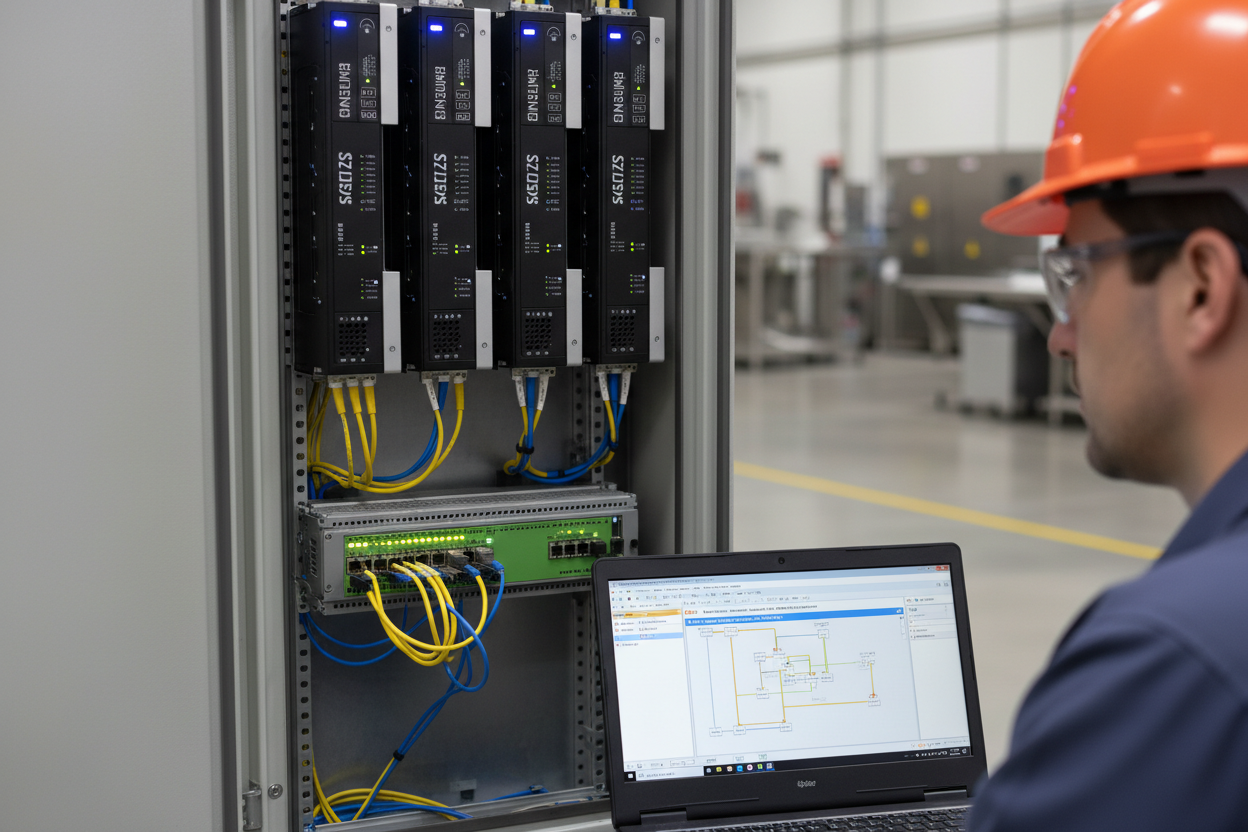
- Step 1: Open Studio 5000 → Controller Properties → Module Properties for the Kinetix 5700 axis.
- Step 2: Navigate to the Fault Log tab. Note the Fault Code (hex) and Fault Timestamp.
- Step 3: Fault Code 0x0204 = Velocity Error Fault. Verify velocity feedback wiring at J13 connector pin 1–4.
- Step 4: Fault Code 0x0810 = Encoder Battery Low. Replace CR2032 battery on absolute encoder. Reset encoder position reference after replacement.
- Step 5: Fault Code 0x1001 = Safe Torque Off (STO) input de-energized. Check 24 VDC supply at STO+ and STO− terminals (≥22 VDC required).
Schneider Lexium 32 stores fault history in internal register MW100–MW109. Read these via Modbus TCP (function code 03). The fault word format: bits 0–3 = fault class, bits 4–7 = fault sub-code. Fault class 4 (0x40) indicates Motor Overtemperature. Fault class 6 (0x60) indicates Encoder Fault. Always verify encoder cable shielding continuity before concluding encoder failure. For Kinetix-family axis modules, see the Kinetix 6000 Integrated Axis Module as a reference platform for fault code architecture.
Network Layer Diagnosis: Finding Jitter and Packet Loss
CIP Motion faults often trace to the network, not the drive. Three specific tests confirm network health quickly.
First, check EtherNet/IP switch port statistics. CIP Motion traffic requires QoS Class of Service (CoS) tagging with DSCP 55 (CIP Motion) and DSCP 46 (CIP real-time). The Allen-Bradley Stratix 5700 managed switch displays per-port discard counters. Any non-zero input discard count on the drive port indicates buffer overflow — reduce background traffic or increase port queue priority.
Second, measure actual RPI jitter with Wireshark. Capture traffic at the controller port. Filter by Ethernet source MAC of the Kinetix 5700 or Lexium 32. CIP Motion requires jitter ≤ 250 µs. Values above 500 µs cause recurring axis faults every 3–10 minutes under load.
- Step 1: Connect laptop to SPAN port on the managed switch. Start Wireshark capture, filter: eth.src == [drive MAC].
- Step 2: Run axis at 50% rated speed for 5 minutes. Export capture to CSV. Calculate standard deviation of inter-packet time.
- Step 3: If jitter > 250 µs, check for multicast flooding. Enable IGMP Snooping on all switches in the CIP Motion VLAN.
- Step 4: Verify the controller NIC runs at 100 Mbps Full Duplex, not Auto-Negotiate. Force both ends to 100FD if jitter persists above 300 µs.
Third, check the Logix 5000 CIP Motion connection status. In Studio 5000, add a Watch Tag for the AXIS_CIP_DRIVE tag. Monitor the .RunningFault, .StartInhibited, and .MotionGroupFault attributes. A .StartInhibited state with no fault code means the controller is waiting for connection re-establishment. Motion Group RPI mismatch is the most common hidden cause.
Drive Tuning Validation After Fault Recovery
Clearing a fault and restarting the axis without tuning validation creates repeat faults within 30 minutes. Follow this sequence after any axis major fault.
For Kinetix 5700, open the Autotune wizard in Studio 5000 (Motion Properties → Tune tab). Set Autotune Mode to "Position Control." Use Inertia Test with a 10% rated torque ramp. The wizard returns Load Inertia Ratio (J_load/J_motor). Accept values 0.1–10. Values above 10 indicate mechanical coupling problems — check gearbox backlash before tuning. After autotune completes, verify Bandwidth Hz setting does not exceed 80 Hz for rigid couplings or 40 Hz for flexible couplings.
For Lexium 32, use SoMove software (v3.3 or later) over the USB diagnostic port. Navigate to Drive → Tuning → Auto-tuning. The drive performs a symmetric velocity step test at 25% rated speed. Check the Kp (position gain) result. Values below 0.5 Hz indicate mechanical stiffness problems. Values above 200 Hz indicate encoder resolution mismatch with screw pitch. Correct the gear ratio parameter (P3.006) before re-testing.
Do not rely on autotune alone for high-dynamic applications. A manual step response test at 10%, 50%, and 100% rated speed confirms tuning across the operating range. Maximum position error at 100% rated speed should stay below 2× the PET value.
Safety Input Logic Faults and STO Recovery
Safe Torque Off (STO) inputs cause 30% of "Axis Faulted" calls in the field. The symptom is identical to a drive hardware fault — the axis faults and will not enable. However, clearing the fault and re-enabling has no effect when STO is not satisfied.
Kinetix 5700 requires both STO inputs (STO-A and STO-B on Safety connector J2, pins 1 and 4) at ≥22 VDC. A single-channel STO fault generates Fault Code 0x1001. A dual-channel STO fault generates 0x1002. If the STO circuit uses a safety relay with delayed dropout, check relay hold-in voltage — below 18 VDC causes intermittent STO trips under vibration.
Lexium 32 STO implementation follows EN/IEC 62061. STO input at terminal CN7 pin 5–6 requires 20–28 VDC for active state. Check the STO_Active bit in drive status register MW0 bit 14. If STO_Active = 0 during normal operation, trace the 24 VDC STO supply cable for ground fault. Use a clamp meter on the STO cable shield — shield current above 50 mA indicates insulation breakdown in a multi-axis cable duct.
Always test STO function after any axis fault recovery. Apply a demand test by removing STO power intentionally. Verify drive torque drops to zero within 20 ms (IEC 62061 Category 3 requirement). Log the STO response time with an oscilloscope. Record the test date and pass/fail result in the maintenance log for IEC 61511 compliance audits.
Conclusion and Action Advice
EtherNet/IP CIP Motion faults follow a predictable pattern. Network jitter above 250 µs, STO input dropout, and post-fault tuning validation failures cause 80% of repeat incidents. Start every diagnostic at the Fault Log, not at the hardware. Decode the fault code before touching any wiring. Confirm network RPI jitter with Wireshark before blaming the drive.
Always run autotune and a manual step response test before returning the axis to production. For Kinetix 5700, keep Studio 5000 and drive firmware versions synchronized — firmware mismatch alone causes false CIP connection errors. For Lexium 32, record MW100–MW109 at every fault event. Five fault records establish a pattern and cut diagnostic time by 60% on the next incident.
Schedule STO proof tests at 6-month intervals and document results. Use the Stratix 5700 managed switch with IGMP Snooping and QoS enabled as the foundation of a reliable CIP Motion network. Safety auditors increasingly request CIP Motion STO test records as part of IEC 62061 compliance reviews.


