Enhancing Industrial Safety: Integrating Combustible Dust Mitigation into Automated Process Control
In the modern industrial landscape, industrial automation is no longer just a tool for throughput; it is a fundamental safety barrier. While automated systems like PLC (Programmable Logic Controllers) and DCS (Distributed Control Systems) drive efficiency, they also introduce unique challenges when managing combustible dust. Without a specialized design, these high-speed processes can inadvertently create the perfect conditions for a catastrophic deflagration.
Identifying the Pervasive Threat of Combustible Dust
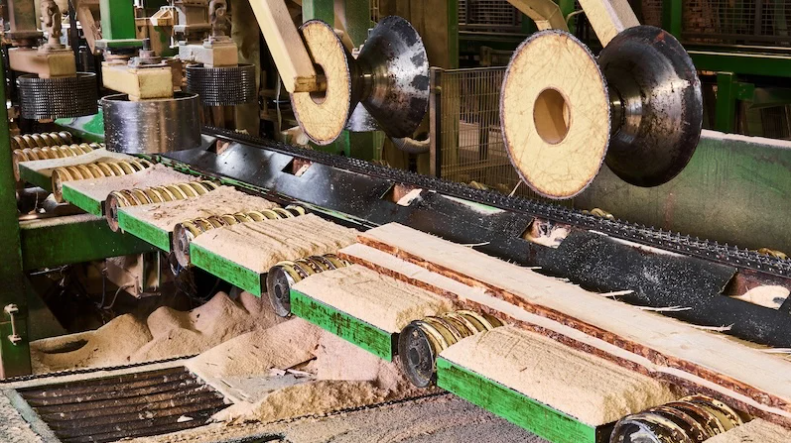
Combustible dust remains one of the most underestimated risks in factory automation. Many common materials—ranging from sugar and flour to aluminum powder and wood—become highly explosive when finely divided and suspended in air. A primary explosion often acts as a mere catalyst. It shakes accumulated dust from overhead beams or light fixtures, leading to a much more devastating secondary explosion. Engineers must treat dust not as a byproduct, but as a volatile fuel source that requires constant monitoring through integrated sensors.
Addressing the Limitations of Industrial Dust Collectors
While industrial dust collectors are essential for regulatory compliance, they are not "set-and-forget" solutions. Inadequate suction or poor filter maintenance can allow dust concentrations to reach the Lower Flosive Limit (LEL). Furthermore, the collector itself can become a localized bomb if it lacks proper explosion venting or chemical suppression systems. Automation professionals should integrate pressure transducers and airflow sensors into the control system to ensure the collector operates within safe parameters at all times.
Utilizing Explosion-Proof Electrical Components for Zone Safety
In hazardous areas, standard electrical enclosures are insufficient. Engineers must specify Explosion-Proof (XP) hardware designed to contain an internal blast and prevent it from igniting the surrounding atmosphere. These components often feature heavy-duty cast aluminum or stainless steel housings with threaded joints. In my experience, relying on XP ratings is critical for high-power equipment like motors and heavy-duty actuators where energy levels are too high for other protection methods.
Implementing Intrinsically Safe Interfaces in Control Loops
For low-power signals, such as those used by temperature or pressure sensors, Intrinsically Safe (IS) design is the gold standard. IS barriers limit the electrical and thermal energy available to a circuit, ensuring that a short circuit or ground fault cannot generate a spark. By utilizing IS interfaces within your PLC architecture, you create a system that is inherently incapable of causing ignition. This approach is often more cost-effective and easier to maintain than bulky XP enclosures for instrumentation.
The Role of Safety Instrumented Systems (SIS)
A Safety Instrumented System (SIS) operates independently from the basic process control. Its sole purpose is to transition the plant to a "safe state" when predefined variables are exceeded. In dust-heavy environments, an SIS might monitor sparks via infrared detectors or detect pressure rises in ductwork. Unlike standard automation, an SIS follows strict SIL (Safety Integrity Level) ratings, ensuring a high probability that the system will function correctly during a critical emergency.
Developing Fail-Safe Logic for Emergency Shutdowns
Generic shutdown sequences can sometimes exacerbate a dust hazard. For instance, abruptly stopping a fan might allow dust to settle in a hot duct, increasing the fire risk. Fail-safe logic ensures that every valve, motor, and damper moves to a predetermined position that minimizes danger. In a well-designed system, the automation will isolate the affected zone while maintaining power to emergency lighting and communication systems, allowing for a coordinated and safe evacuation.


