Coriolis Mass Flow Meter Field Configuration, Zero Calibration, and Fault Diagnosis
Why Coriolis Meters Drift After Installation
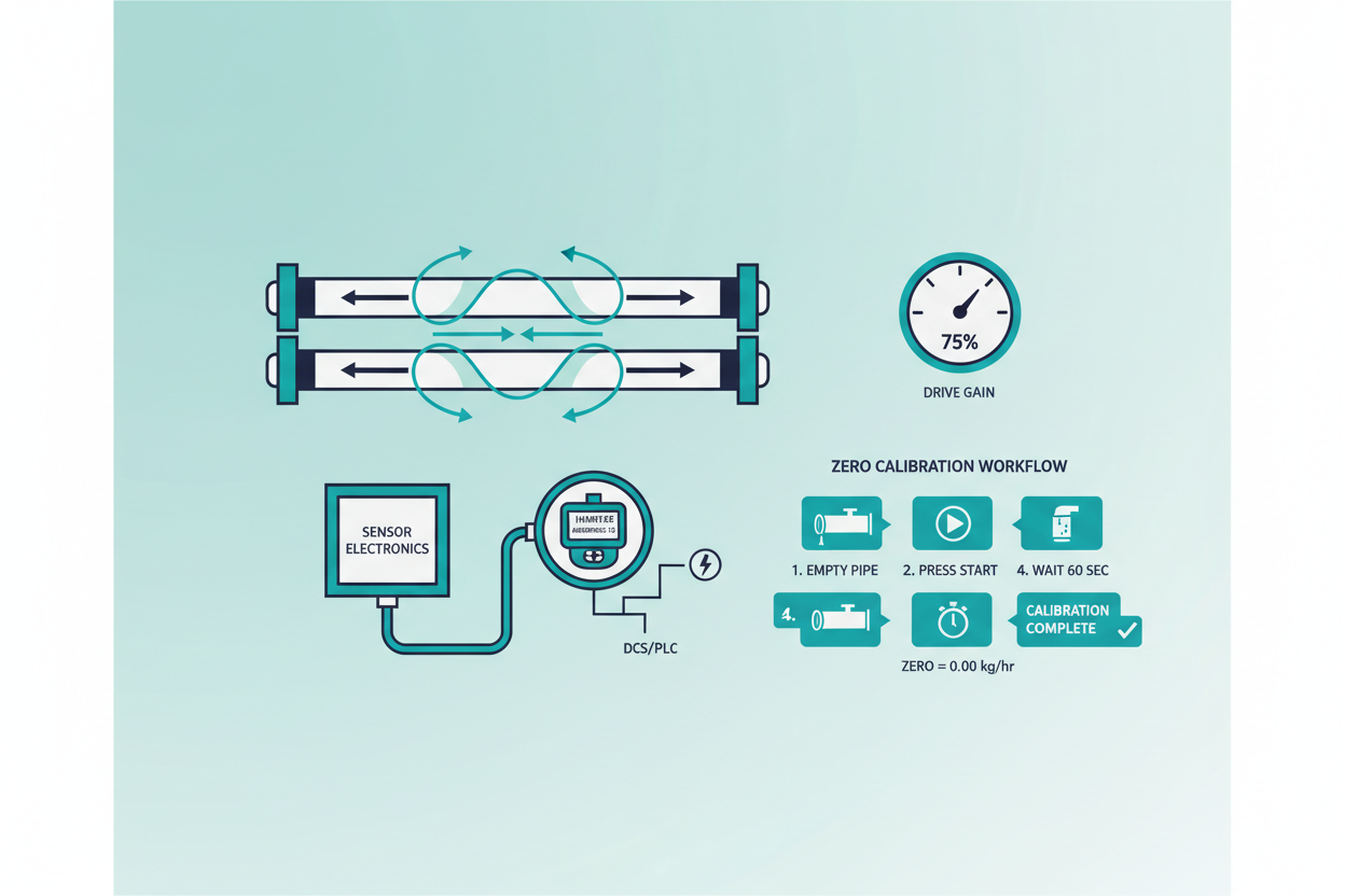
Coriolis meters measure mass flow through the phase shift between two vibrating tubes. A Coriolis tube vibrates at its natural resonant frequency — typically 80 to 130 Hz for a 2-inch sensor. Any mechanical stress introduced during installation distorts this resonance baseline. The Emerson Micro Motion 2700 transmitter stores the Raw Zero value at commissioning. If pipe stress shifts the tube resting position, the Raw Zero drifts and all subsequent flow readings carry a systematic offset.
Field experience shows that flange misalignment greater than 1.5 mm introduces a zero offset equivalent to 0.05% of full-scale on a 100 kg/min meter — roughly 50 g/min of false flow at shutoff. The GE Panametrics CFS Series transmitter uses the same phase-shift principle but applies a digital signal processor with adaptive filtering to reduce noise floor.
Both platforms require the same mechanical discipline during installation. First, support the process piping independently — never let the meter carry pipe weight. Second, align flanges within 0.5 mm lateral and 0.1-degree angular tolerance. Third, avoid installing the meter directly downstream of a control valve without at least 10 pipe diameters of straight run.
Zero Trim Procedure Using HART
Zero trim corrects the Raw Zero baseline after installation stress is eliminated. This procedure requires zero-flow conditions — the tube must be completely filled with process fluid at operating temperature and pressure. Never perform zero trim with an empty or partially filled tube. The resulting Raw Zero on a properly installed 2-inch Micro Motion sensor should fall within ±10 nanoseconds of the factory baseline.
- Step 1: Isolate the meter. Close upstream and downstream block valves. Verify zero flow with a downstream visual check or secondary instrument.
- Step 2: Wait for thermal stabilization. Allow 15 minutes after the process reaches operating temperature. Temperature gradients across the sensor body introduce apparent flow signals.
- Step 3: Connect a HART communicator or use AMS Device Manager. Navigate to Micro Motion 2700 Service menu → Zero Calibration → Start Zero.
- Step 4: The transmitter samples tube phase shift for 60 seconds. The display shows "Zeroing In Progress." Do not interrupt the process.
- Step 5: Read the resulting Raw Zero value. Accept if within ±10 ns. If outside this range, inspect piping for residual stress — recheck flange torque sequence using the cross-pattern tightening method.
- Step 6: Verify the 4–20 mA output reads 4.00 mA at zero flow. On the Panametrics CFS, send HART universal command 3 to read Primary Variable and confirm PV = 0.000 kg/min within ±0.05%.
Drive Gain — The Hidden Fault Indicator
Drive Gain is the transmitter’s effort to maintain tube vibration at resonant amplitude. A healthy Micro Motion 2700 shows Drive Gain between 15% and 40% during normal operation. Drive Gain rising above 85% indicates a serious process condition or mechanical fault. The transmitter cannot sustain resonance and eventually declares a Slug Flow alarm — code A105 on the Micro Motion 2700 fault register.
Two-phase flow is the primary cause of elevated Drive Gain. Gas entrainment in a liquid process dramatically reduces tube density, damping the oscillation. On the GE Panametrics CFS, the same condition manifests as a Tube Not Full diagnostic flag in the device status register (bit 5 of the Process Alarm Word). Engineers often misdiagnose this as transmitter failure. However, two-phase flow detection should trigger a process review first — look for cavitation at the upstream control valve, vortex shedding from a partially open bypass valve, or a flash point condition caused by low backpressure.
Other causes of high Drive Gain include:
- Wax or hydrate buildup inside the tubes — perform a hot-water purge and compare Drive Gain before and after.
- Tube corrosion or erosion — request a baseline Drive Gain trend from the historian and look for a gradual increase over weeks.
- Loose junction box connections — vibration at the sensor housing can introduce noise, falsely elevating the Drive Gain calculation.
Six-Step Fault Isolation Workflow
Follow this structured sequence when a Coriolis meter produces erratic readings or a fault alarm. The Micro Motion 2700 and GE Panametrics CFS share a common diagnostic hierarchy.
- Step 1: Read the active fault register. On Micro Motion 2700, use HART command 48 (Read Additional Status). On GE Panametrics CFS, read the Extended Device Status byte. Categorize the fault as a process alarm or a hardware alarm.
- Step 2: Check Drive Gain. Below 85% → the tube is vibrating normally. Above 85% → suspect two-phase flow or fouling. Above 100% → tube may be cracked or sensor coil damaged.
- Step 3: Verify tube temperature. The RTD inside the sensor reports tube temperature via HART PV3. A temperature reading more than 15°C away from process temperature indicates an RTD wiring fault or sensor damage.
- Step 4: Perform a zero stability check. With zero flow, monitor the Raw Zero value for 5 minutes. Drift greater than ±5 ns/min confirms mechanical stress or a loose sensor mounting.
- Step 5: Check the 4–20 mA loop. Apply a 250-ohm HART resistor in the loop. Verify the loop current matches HART PV within ±0.05 mA. A discrepancy indicates a D/A converter fault inside the transmitter.
- Step 6: Compare density reading against a reference. On the Micro Motion 2700, HART PV2 = Line Density. Compare against a lab sample. Density error above ±2 kg/m³ confirms tube damage or significant coating accumulation.
Transmitter Configuration: Key Parameters
Correct configuration prevents systematic errors. On the Emerson Micro Motion 2700, verify these parameters after commissioning:
- Flow Direction: Set to Forward if the process always flows in one direction. Bidirectional metering requires setting Flow Direction to Absolute or Bidirectional to avoid negative-flow false readings.
- Mass Flow Cutoff: Factory default is 0.5% of the calibrated full-scale flow. Reduce to 0.2% for custody transfer applications to prevent false accumulation during near-zero flow periods.
- Slug Flow Duration: Default is 0 seconds. Increase to 5 seconds for processes with brief gas slugs to prevent unnecessary control upsets.
- Damping: Factory default is 0.04 seconds. Increase to 0.16 seconds for noisy pipeline applications to smooth the 4–20 mA output without affecting measurement accuracy.
On the GE Panametrics CFS, set the Low Flow Cutoff to 2% of span to eliminate false accumulation at pump shutdown. Confirm the Output Update Rate matches the DCS scan rate — a 100 ms output update into a 500 ms DCS scan cycle wastes four out of five data points and may cause PID instability.
Conclusion and Action Advice
Coriolis meters deliver exceptional accuracy — typically ±0.1% mass flow — only when installation mechanics and transmitter configuration are correct. Address pipe stress at the flange before performing zero trim. Use HART commands 3 and 48 systematically to separate process alarms from hardware faults. Monitor Drive Gain as a leading indicator: a trend rising from 25% to 60% over three months warns of tube fouling long before accuracy degrades measurably.
On Emerson Micro Motion 2700 systems, set the Slug Flow Duration to 5 seconds and the Mass Flow Cutoff to 0.2% for custody transfer service. On GE Panametrics CFS systems, confirm the Output Update Rate matches your DCS cycle time. These small configuration choices determine whether a high-performance sensor delivers its rated accuracy or introduces systematic bias into your process accounting.
Author: Chen Hao is an industrial automation engineer with over 10 years of experience in PLC, DCS, and control systems.


