Condensate Pot Installation and Impulse Line Commissioning for Steam Process DP Measurement: Emerson Rosemount 3051S and Woodward 505 Integration
Why Condensate Pots Are Critical in Steam DP Loops
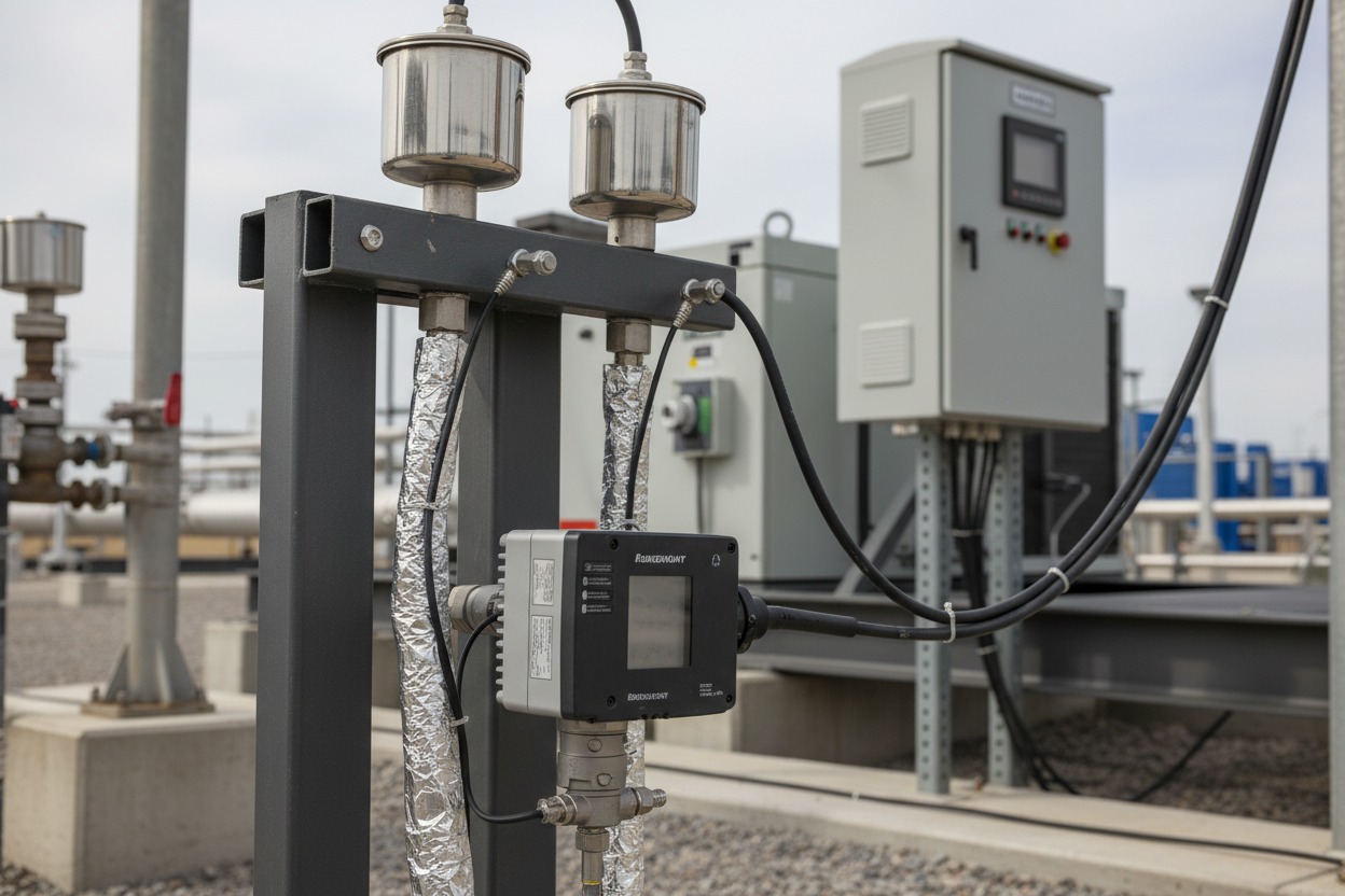
Steam process lines present a unique measurement challenge. The process fluid is compressible vapor at elevated temperature. Standard DP transmitters, such as the Emerson Rosemount 3051S, require liquid-filled impulse lines to transmit pressure accurately. Without a condensate pot, steam condenses unpredictably inside the impulse line. The resulting liquid column height varies with ambient temperature, insulation condition, and process flow rate. This creates a variable hydrostatic head error that can exceed 5% of span on a 250 mmH2O DP range — enough to corrupt flow calculations and trigger false low-flow alarms on Woodward 505 governor pressure inputs.
Install condensate pots at the high-pressure and low-pressure taps to create a controlled, stable liquid reference column. The pot volume must be large enough that condensate level changes during the worst-case process transient do not shift the reference head. Rosemount recommends a minimum condensate pot volume of 500 mL for steam lines above 10 bar. Both pots must be installed at identical elevations — height difference between HP and LP pots introduces a constant static head error equal to: ΔP_error = ρ_condensate × g × Δh.
Condensate Pot Sizing and Elevation Rules
Condensate pot selection depends on three parameters: process pressure rating, condensate density, and impulse line fill volume. For a 50 bar saturated steam application with a Rosemount 3051S CD3 (3-inch flange, ANSI 600), use a 316 SS condensate pot rated for 100 bar at 300°C minimum. Internal volume must exceed the total impulse line fill volume by a factor of 3.
Elevation rules are non-negotiable. Mount both condensate pots at the same elevation within ±2 mm. Run impulse lines from the condensate pots downward to the Rosemount 3051S transmitter at a minimum slope of 1:10 (10 mm drop per 100 mm horizontal run). This ensures self-venting of any steam that flashes inside the impulse line during low-flow conditions. The transmitter must always be below the condensate pots. Inverted installations are not recommended for high-accuracy Woodward 505 speed/load governor applications where pressure input accuracy directly affects droop control performance.
Freeze Protection Heat Tracing Design
Condensate inside impulse lines freezes when ambient temperature drops below 0°C. Frozen impulse lines produce a stuck PV — the transmitter reads the last live value before freeze-up, then holds it indefinitely. The Rosemount 3051S itself operates to −40°C, but the impulse line liquid column fails first. Apply electric heat tracing (EHT) or steam tracing to all impulse lines in outdoor or unheated locations.
For electric heat tracing, select a self-regulating trace cable rated for 10 W/m at 10°C ambient. Apply trace along the full impulse line length and wrap with aluminum foil tape before mineral wool lagging. Set the EHT control thermostat to activate at +5°C. Do not allow the impulse line temperature to exceed 60°C — above this value, condensate flashes back to steam and disrupts the liquid reference column. Woodward 505 installations in cold climates (below −10°C) must also heat-trace the manifold valve block. Frozen manifold valves prevent the zero-trim procedure during calibration checks and delay maintenance significantly.
Six-Step Commissioning Procedure
- Step 1: Fill both condensate pots with demineralized water or process condensate before applying steam pressure. Use a hand pump through the fill plug. Confirm liquid level at the sight glass (where fitted) or measure fill volume against calculated impulse line capacity.
- Step 2: Open root valves slowly — no more than one quarter-turn per 30 seconds on lines above 20 bar. Allow condensate pots to reach thermal equilibrium for 15 minutes. During this period, the Rosemount 3051S output will drift as the condensate column stabilizes. Do not attempt zero-trim during this period.
- Step 3: Close the equalizing valve on the 5-valve manifold. Isolate the LP impulse line with the LP block valve. Confirm the HP-only reading on the Rosemount 3051S HART output (HART Command 1: Primary Variable). Record this value as the static offset reference.
- Step 4: Open the equalizing valve to connect HP and LP chambers. Both sides see identical pressure. The differential output must read 0.000 ±0.010 inH2O (0.000 ±2.5 Pa). If deviation exceeds this, adjust elevation of the LP condensate pot or trim the transmitter zero using HART Command 35 (Zero Trim). Document the applied zero offset value.
- Step 5: Close the equalizing valve and reopen the LP block valve. Apply a known DP using a dead-weight tester or precision pressure calibrator at the HP tapping with LP at atmospheric. Confirm the Rosemount 3051S output matches the applied pressure within ±0.065% of calibrated span (3051S reference accuracy class).
- Step 6: Return the 5-valve manifold to normal service position. Monitor Rosemount 3051S output via HART for 30 minutes under live steam flow. Verify the Woodward 505 pressure input (4–20 mA, typically mapped to 0–10 bar gauge) reads stable with less than ±0.5% variation at steady load. Record all as-found and as-left values in the loop calibration data sheet.
Common Faults and Their Signatures
- Fault 1 — Partial freeze of LP impulse line: Transmitter reads high DP (apparent high flow) during cold nights and recovers after heat tracing restores the liquid column. This pattern repeats with diurnal temperature cycles.
- Fault 2 — Condensate pot overfill due to blocked vent: Rosemount 3051S reads a constant negative DP offset even with zero process flow. Calculated offset equals ρ_water × g × h_overflow, where h_overflow is the distance liquid rose above the reference level.
- Fault 3 — Air entrainment after maintenance: DP signal shows high-frequency oscillation at 0.5–2 Hz without corresponding process flow variation. Purge the impulse lines by opening the drain plugs at the lowest point for 30 seconds with LP block valve closed.
- Fault 4 — Condensate pot mounting bracket corrosion: Zero-offset drifts slowly over 3–6 months without any maintenance event. Inspect mounting hardware annually and apply anti-seize compound to all stainless steel fasteners on outdoor installations.
Conclusion and Action Advice
Condensate pot installation for Emerson Rosemount 3051S DP transmitters on steam lines is a precision task. Size pots for minimum 500 mL volume at pressures above 10 bar. Mount both pots at identical elevations within ±2 mm to eliminate static head error. Slope impulse lines at 1:10 downward to the transmitter to guarantee self-venting. Apply electric heat tracing set at +5°C activation with a 60°C upper limit to protect the liquid reference column in cold environments.
Follow the six-step commissioning procedure without skipping the 15-minute thermal equilibrium wait — premature zero-trim locks in a systematic offset that propagates through the Woodward 505 governor control calculation. Document as-found and as-left calibration values at every maintenance visit. A condensate pot installation completed without a calibration record is an installation waiting to cause an unexplained trip.
Author: Cao Jianjun is an industrial automation engineer with over 10 years of experience in PLC, DCS, and control systems.


