Complementary Split Range Control (CSRC): Engineering Precise Process Variable Management with Dual Actuators
What Is Complementary Split Range Control and Why Use It?
Complementary split range control is a control strategy that deploys two actuators working in opposite directions to regulate a single process variable with high precision. Standard single-valve control cannot achieve fine resolution when different media streams must blend at precise ratios. CSRC solves this by assigning each actuator a complementary role: when one valve opens, the other closes by the same proportion.
This approach appears in heat exchangers, blending systems, reactor temperature control, and gas conditioning units. The Foxboro FCP270 Field Control Processor and Allen-Bradley ControlLogix PLCs both provide native function blocks that implement split range output logic directly in the controller.
First, consider why a single valve fails in these applications. A valve sized to handle maximum flow operates at very low open percentages during normal duty. At 5% to 10% opening, flow characteristic curves become non-linear and positioner hysteresis causes limit cycling. Control quality degrades significantly in this low-opening region.
How CSRC Works: The Inverse Relationship Between Two Actuators
In a CSRC system, the PID controller produces a single output signal — 4 to 20 mA or 0 to 100% in digital systems. This signal routes to both control valves simultaneously. However, each valve responds to a different portion of the output range, and their responses are inverse.
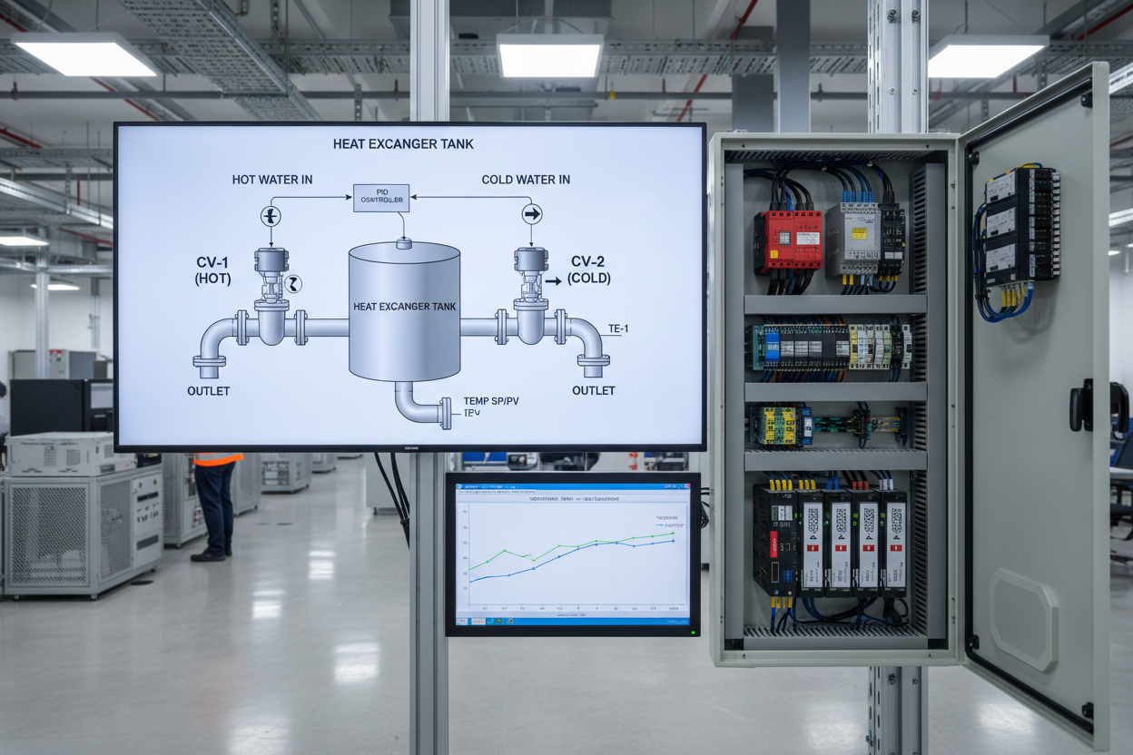
Consider a tank temperature control system using hot and cold water streams. The Allen-Bradley 1756-OF8 8-Channel Analog Output Module delivers the complementary signals to both valve positioners:
- Step 1: The cold water valve drives from fully open at 0% controller output to fully closed at 100% output. It passes maximum cold water when process temperature is too high.
- Step 2: The hot water valve receives an inverse signal — fully closed at 0% output and fully open at 100% output. It passes maximum hot water when temperature is too low.
- Step 3: At 50% controller output, both valves sit at 50% opening. Equal proportions of hot and cold water enter the tank, and the setpoint is maintained by continuous adjustment around this midpoint.
- Step 4: As the controller output changes, both valves adjust simultaneously and inversely. Total flow rate stays relatively stable while the hot-to-cold ratio shifts. This maintains precise temperature control without the flow disturbances that single-valve systems create.
PID Configuration in Allen-Bradley ControlLogix and Foxboro I/A
Implementing CSRC in Allen-Bradley ControlLogix uses math function blocks to generate two complementary output signals from the PID CV value. The hot water valve command equals CV directly: HV_CMD = CV%. The cold valve command is the complement: CV_CMD = 100% – CV%. Both signals route to independent valve positioners via the Allen-Bradley 1756-OF8I Isolated Analog Output Module.
Moreover, a dead band at the midpoint — typically 45% to 55% output range — prevents both valves from hunting simultaneously at setpoint. Within this dead band, small controller output changes are absorbed without moving either valve. This reduces actuator wear significantly during stable operation.
Foxboro I/A Series implements CSRC through the native SPLT (Split Range) function block within the Foxboro I/A Series FCM10E Fieldbus Communications Module architecture. It accepts a single input and produces two complementary outputs with configurable split points, dead bands, and valve characterization curves. The Foxboro SPLT block also supports non-symmetric splitting — for example, assigning 0% to 40% output to the cold valve and 60% to 100% to the hot valve, with a dead band from 40% to 60%.
Non-symmetric configuration is useful when the two media streams have different flow capacities. Tuning the split points to match the process gain on each side improves loop stability and reduces overshoot after setpoint changes.
Valve Sizing, Selection, and Fail-Safe Configuration
Valve sizing for CSRC differs from single-valve applications. Each valve handles the full design flow at 100% opening, but normal operating duty concentrates in the 30% to 70% opening range. Oversized valves create control problems at low openings. Undersized valves reach their flow limit before the controller reaches 100% output. Equal percentage characteristic valves are the standard choice — this characteristic provides consistent control gain across the mid-range operating zone.
Furthermore, both valves in a CSRC pair must use matching positioners with equal accuracy and hysteresis specifications. Mismatched positioners create asymmetric control — the loop performs well in one direction but oscillates in the other. In reactor temperature control, the preferred fail-safe is to fully open the cooling valve and fully close the heating valve on instrument air or power loss. This moves the process toward a safe cold condition.
Commissioning and Tuning a CSRC Loop
- Step 1: Stroke each valve fully open and closed. Verify that the as-found position matches the commanded position within ±2% for globe valves or ±1% for high-performance butterfly valves.
- Step 2: Apply the complement function in manual mode at 25%, 50%, and 75% output. Verify that valve A opens to these values and valve B opens to 75%, 50%, and 25% respectively.
- Step 3: Enable automatic control with conservative initial tuning — proportional gain of 0.5 and integral time of 60 seconds. Observe loop response to a small setpoint step of 2% to 5% of span.
- Step 4: Increase proportional gain gradually until the loop achieves a quarter-decay response. Reduce integral time until the offset disappears within three to five loop cycles.
- Step 5: Test the response to a large setpoint change of 20% of span. Verify that the split range transition at the midpoint does not cause a bump or oscillation — this transition is the most common source of CSRC loop instability.
Therefore, pay close attention to PID output behavior as it crosses the 50% split point. Any discontinuity at this point indicates a mismatch between the split range configuration and the actual valve response curves, which requires adjustment before the loop is approved for automatic service.
Conclusion and Action Advice
Complementary split range control is a powerful technique for achieving precise, stable control of temperature and composition where a single valve cannot meet required performance. The inverse actuator relationship keeps both valves in their accurate mid-range operating zones and maintains stable total flow. Foxboro I/A Series and Allen-Bradley ControlLogix provide proven native implementations that simplify configuration and commissioning. Engineers implementing CSRC should focus on matched valve sizing, identical positioner specifications, symmetric split point configuration, and careful tuning through the midpoint transition to deliver reliable control loop performance.
Author: Wang Jiaqiang is an industrial automation engineer with over 10 years of experience in PLC, DCS, and control systems.


