Woodward MicroNet TMR Gas Turbine Governor PID Tuning and Overspeed Trip Validation
MicroNet TMR Architecture and Speed Control Overview
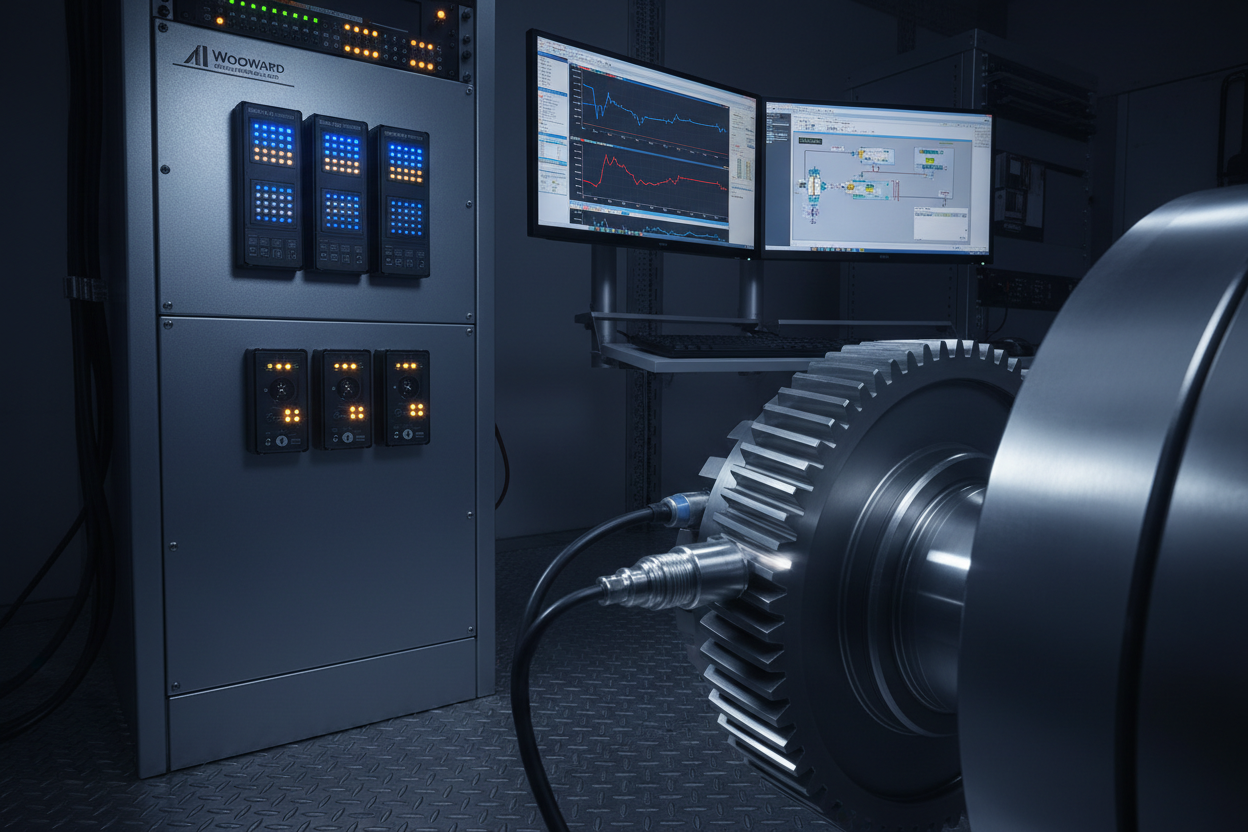
The Woodward MicroNet TMR runs a triple-modular redundant architecture. Three independent controllers execute speed control logic in parallel. A 2oo3 voter selects the median output for fuel actuator command. This design meets IEC 61511 SIL 2 requirements for overspeed protection. Each CPU module runs at 10 ms task cycle. Speed sensor inputs use passive MPU pickups on a 60-tooth gear ring. Typical output frequency ranges from 0 Hz at standstill to 2,500 Hz at 3,000 RPM rated speed.
ABB 800xA integrates with MicroNet TMR via Modbus TCP. Register 40001 holds actual speed (0–4,000 RPM, 1 RPM/count). Register 40005 holds fuel valve position (0–100%, 0.1%/count), updated every 100 ms.
PID Tuning for Speed Reference Tracking
Woodward MicroNet TMR uses a parallel PID structure. The speed PID parameters are GAIN_P (proportional), RESET_I (integral in repeats/second), and RATE_D (derivative in seconds). Default factory values are GAIN_P = 20, RESET_I = 2.0 r/s, RATE_D = 0.02 s. Use the Woodward Watch Window software to adjust parameters live. Connect via RS-232 at 115,200 baud. Enable the trend recorder at 10 ms sample rate before any tuning change.
- Step 1: Record the baseline speed step response. Apply a 50 RPM step at 3,000 RPM. Measure rise time, overshoot, and settling time from the trend plot.
- Step 2: If overshoot exceeds 1.5% (45 RPM), reduce GAIN_P by 10% increments. Wait 5 minutes between changes. Confirm the trend at each step.
- Step 3: If settling time exceeds 3 s, increase RESET_I by 0.2 r/s increments. Limit RESET_I to 4.0 r/s maximum for single-shaft turbines.
- Step 4: Enable RATE_D only if speed oscillation persists after proportional and integral tuning. Increase from 0.01 s in 0.005 s steps. Use an 80 Hz low-pass filter on the speed signal input when enabling derivative.
- Step 5: Verify load acceptance. Apply a 20% sudden load increase. Confirm speed deviation stays within ±3% of rated speed and recovers in under 5 s.
Droop Configuration and Load Sharing
Droop controls load sharing between parallel turbines. A 5% droop allows a 150 RPM speed decrease at 3,000 RPM rated speed when load increases from zero to full. Set droop to 0% (isochronous) only in island mode with no parallel units. For parallel operation, set droop to 4–5% via Watch Window — Speed Control — Load Sharing. The Woodward digital load sharing speed control module provides dedicated load sharing logic for multi-unit parallel operation.
Incorrect droop causes load hunting at 0.5–2 Hz. ABB 800xA signal groups log active power and speed simultaneously. A load hunting signature shows sinusoidal active power oscillation with 180° phase offset between parallel units. Verify the actuator feedback loop — the MicroNet TMR reads position via a 4–20 mA LVDT signal from the Woodward ProAct electric valve actuator. Wire break alarm triggers at 3.8 mA. Set ACT_POS_GAIN to 12–15 to avoid position loop hunting.
Overspeed Trip Proof Test: 2oo3 Voting Verification
IEC 61511 requires annual proof testing of the overspeed trip function for SIL 2 gas turbine protection. The MicroNet TMR provides a dedicated overspeed test mode allowing each MPU channel to be tested individually without tripping the turbine.
- Step 1: Notify operations. Obtain permit-to-test. Confirm turbine is at steady-state rated speed ±0.5%.
- Step 2: In Watch Window, navigate to Overspeed Test — Channel A Inhibit. Enable inhibit on Channel A. Confirm the Channel A status LED turns amber on the MicroNet TMR front panel.
- Step 3: Inject a simulated overspeed signal into Channel A MPU input using a frequency generator. Set frequency to correspond to 110% of rated speed (3,300 RPM = 3,300 Hz for 60-tooth gear). Confirm Channel A overspeed alarm activates but no trip occurs. The 2oo3 voter requires two channels to agree for a trip.
- Step 4: Release Channel A inhibit. Repeat Steps 2–3 for Channel B, then Channel C independently.
- Step 5: For the combined test, inhibit two channels simultaneously. Inject the overspeed signal into the remaining active channel. Confirm trip output activates within 200 ms. Verify the trip output reaches the ABB 800xA DI card. Log the response time from the ABB 800xA SOE historian with 1 ms resolution.
- Step 6: Record all as-found and as-left values. Document the test in the IEC 61511 proof test record. Confirm PFDavg recalculation is within SIL 2 range (1×10⁻³ to 1×10⁻²).
Conclusion and Action Advice
MPU signal quality directly affects governor stability. MicroNet TMR monitors MPU_AMPLITUDE (healthy range 2,000–8,000 mV peak), MPU_NOISE_RATIO (advisory alarm at 15%), and MPU_FREQUENCY_ERROR. Amplitude below 1,000 mV indicates excessive gap. Standard gap is 0.75–1.25 mm for a 60-tooth gear. Use shielded twisted-pair cable grounded at the controller end only. Terminate at terminal block TB3.
Woodward MicroNet TMR governor tuning requires a systematic approach. Start with baseline trend recording before any parameter change. Tune GAIN_P first, then RESET_I, then RATE_D. Verify droop matches the parallel operation mode using the Woodward load sharing speed control. Perform the annual overspeed proof test using the built-in channel inhibit function. Integrate ABB 800xA SOE logging to document trip response times. The Woodward 505 digital governor provides an alternative platform for single-shaft turbine applications where TMR redundancy is not required. These steps maintain SIL 2 integrity and extend turbine availability between outages.
Author: Liu Yang is an industrial automation engineer with over 10 years of experience in PLC, DCS, and control systems.


