Emerson Ovation Epro + Foundation Fieldbus: Achieving Seamless Diagnostic Integration
Q: How Does Foundation Fieldbus Integrate with Emerson Ovation Epro?
Foundation Fieldbus (FF) replaces 4–20 mA analog wiring with a single digital bus, allowing each field device to transmit multiple variables, device diagnostics, and configuration data. FF also supports function block execution in field devices, enabling PID loops to execute inside the field transmitter or valve positioner — reducing controller loading and improving response time.
Emerson Ovation Epro integrates FF H1 segments via dedicated Fieldbus Communication Controllers (FCC) that bridge the FF H1 segments and the Ovation controller network. The Emerson Ovation 5X00226G02 I/O Interface Module provides the I/O connectivity layer for the Ovation Epro DCS in Foundation Fieldbus-integrated installations. The Foxboro I/A Series FCM10E Fieldbus Communications Module and Foxboro FBMSVL Fieldbus Module are common FF interface modules used in Foxboro I/A Series DCS systems that share FF H1 segments with Ovation in brownfield integration projects.
Q: How Do I Commission an FF H1 Segment on Ovation Epro?
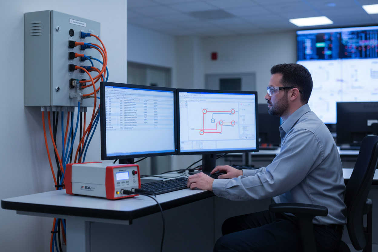
- Step 1: Perform a segment test before connecting field devices. Use a Fieldbus Intrinsically Safe Analyzer (FISA). Measure the capacitance, inductance, and loop resistance. Confirm values are within Fieldbus Foundation specification. Maximum segment length is 1900 metres without repeaters.
- Step 2: Check the Fieldbus junction boxes. Ensure each spur length does not exceed 1 metre for IS applications (up to 30 metres for non-IS). Terminate each spur with the correct resistor value.
- Step 3: Connect field devices one at a time. After each device connection, monitor the LAS commissioning log in Ovation. Confirm the device transitions from PFO (Powered Off) to Online (Active). Record the node address assigned by the LAS.
- Step 4: In Ovation Workstation, use the FF Configurator tool. Verify the Device Revision and DD version match the installed device. Import the latest DD file if a mismatch is detected.
- Step 5: Configure function blocks. Place the AI (Analog Input), PID, and AO (Analog Output) blocks. Connect the blocks per the P&ID logic. Assign the FF channel parameters to match the device I/O.
- Step 6: Enable resident diagnostics in each field device. Configure alarm thresholds for signal saturation, device malfunction, and communication failure. Route these alarms to the Ovation operator graphics.
Q: How Do I Integrate Foxboro and Honeywell Devices on Ovation FF Segments?
Both Foxboro and Honeywell manufacture FF-certified field instruments. When integrating these devices on Ovation Epro, verify Interoperability Test Kit (ITK) compliance — the Fieldbus Foundation maintains a registry of ITK-tested devices.
Q: What should I know about Foxboro FF transmitters?
The AI function block provides the primary PV value. The device supports Out-of-Service (OOS) mode via FF, allowing the maintenance technician to take the device offline without generating spurious alarms. The OOS command is issued from the Ovation operator interface.
Q: What about Honeywell FF devices?
Honeywell field devices use a slightly different parameter naming convention. The PV is mapped to the OUT parameter of the Analog Input block. Secondary variables (such as sensor temperature) are accessed via the transducer block. Consult the Honeywell FF Device Description file for the exact parameter paths.
Mixing FF devices from different manufacturers on the same segment requires careful verification. Some devices implement proprietary function blocks that are not universally supported. Check the FF registration database before ordering mixed-vendor segments.
Q: How Do I Manage LAS Performance and Tune Communication?
The Link Active Scheduler (LAS) manages all communication on an FF H1 segment. The Ovation FCC typically operates as the primary LAS. The LAS allocates communication time slots for each scheduled macrocycle. The typical macrocycle time for a 4-device segment is 500 ms.
Q: What causes communication delays and how do I diagnose them?
- VCR utilization: Each FF device consumes VCR (Virtual Communication Relationship) resources. The H1 physical layer supports a maximum of 240 VCRs per segment. Most field devices consume 2–3 VCRs each. A near-full VCR table causes communication delays and timeout errors.
- Delta-t jitter: Monitor the delta-t parameter in the Ovation diagnostics. Delta-t represents the time variance between scheduled and actual message delivery. A delta-t above 50 ms indicates excessive jitter, typically caused by too many devices on the segment or electromagnetic interference on the bus.
What Is the Key Action Advice?
Follow a structured commissioning approach: segment testing first, then device-by-device connection, function block configuration, and diagnostics enablement. Mixed-vendor integration is feasible but requires careful ITK compliance verification. Establish a baseline of communication performance metrics during commissioning — document the macrocycle time, VCR utilization, and delta-t values. Compare these against quarterly trend data. Any degradation above 15% triggers a maintenance work order. Schedule annual FF segment health checks as part of the plant’s preventive maintenance calendar.
Author: Zhang Ming is an industrial automation engineer with over 10 years of experience in PLC, DCS, and control systems.


