Mastering Automated Door Control: A Practical Guide to Ladder Logic and PLC Integration
In the world of industrial automation, automated entry systems are more than just a convenience. They represent a fundamental application of control systems that balance sensor input, motor output, and safety logic. Understanding how to program these sequences is essential for any engineer working with factory automation. This guide breaks down the logic behind a sliding door system using XG5000 PLC (Programmable Logic Controller) mapping.
Establishing the Operational Sequence for Automated Entry
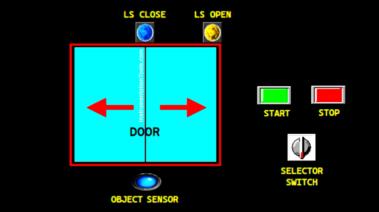
A reliable automated door follows a specific, repeatable sequence to ensure safety and efficiency. First, the system initializes variables upon startup, ensuring the door starts in a closed position. When an approach sensor detects an object, it triggers the motor to open the door. A limit switch confirms when the door reaches its fully open state. Subsequently, the system holds the door for five seconds before reversing the motor to close it. This standard loop ensures smooth traffic flow within an industrial facility.
Implementing Power Control and System Latching
In PLC programming, the first priority is establishing a robust start/stop mechanism. Using Rung 1 of the ladder logic, we map the START button (P0000) to a memory bit named SYSTEM_ON (M0000). By applying a latching circuit, the system remains energized even after the operator releases the button. Conversely, pressing the STOP button (P0001) breaks the circuit, immediately setting the memory bit to a LOW state. This "seal-in" logic is a cornerstone of safe industrial automation design.
Managing Manual Overrides and Opening Sequences
Efficiency often requires manual overrides, such as keeping a door open for maintenance or high-volume deliveries. We achieve this through a HOLD_DOOR (M0001) memory bit linked to a physical selector switch (P0005). When the system is active and the sensor (P0002) triggers, the MOTOR_SLIDER_OPEN (P0040) output engages. The motor stays active until the LS_DOOR_OPEN (P0003) limit switch sends a HIGH signal. This ensures the motor does not strain against the door frame once the opening process completes.
Timing and Automated Closing Logic
Once the door reaches the open limit, a timer (T000) begins a 5-second countdown. However, the system must be smart enough to pause this timer if the HOLD_DOOR mode is active. After the timer expires, the MOTOR_SLIDER_CLOSE (P0041) output activates. Like the opening sequence, this output utilizes latching logic to maintain movement. Finally, the LS_DOOR_CLOSE limit switch terminates the operation once the door reaches its home position, resetting the cycle for the next detection.
Expert Insight: The Importance of Limit Switch Reliability
From my experience in the field, the most common failure point in door control systems isn't the code; it is the physical limit switch. Environmental debris in a factory can often interfere with mechanical switches. Therefore, I highly recommend using inductive proximity sensors or heavy-duty magnetic reed switches for the LS_DOOR_OPEN and LS_DOOR_CLOSE inputs. These non-contact solutions significantly reduce maintenance downtime and improve the overall reliability of your factory automation setup.


