Why RTD Sensors Must Be Installed Downstream of Orifice Plates
The Core Problem: Vortex Streets and Pressure Interference
Orifice plate flow meters rely on precise differential pressure measurement. Any upstream disturbance degrades accuracy. A thermowell installed upstream generates a predictable pattern of alternating vortices known as a von Kármán vortex street. These vortices create oscillating pressure waves that propagate upstream and corrupt the differential pressure signal at the orifice tapping points.
Flow engineers at Yokogawa routinely trace 1.5–3% flow measurement errors to a single root cause: incorrect RTD placement before the orifice plate. The pressure fluctuation frequency from a thermowell scales with flow velocity, following the Strouhal relationship. At typical process velocities of 3–8 m/s, this frequency falls within the response bandwidth of most DP transmitters, which means the transmitter cannot filter it out automatically. The Yokogawa DPharp EJA Series Pressure Transmitter is a high-accuracy DP transmitter widely used in orifice plate metering systems where upstream flow disturbances must be eliminated to achieve rated accuracy.
Therefore, ISO 5167-1 and the ASME MFC-3M standard both require temperature elements to be positioned downstream of the primary flow element. This is not a recommendation — it is a metering system integrity requirement.
The Physics Behind Downstream Placement
A thermowell inserted into a pipe cross-section acts as a bluff body. Flow separation at the thermowell creates two alternating low-pressure zones on opposite sides of the stem. This shedding is periodic and repeatable, but it introduces a fluctuating pressure component into the upstream flow field.
When the thermowell sits upstream of the orifice plate, three failure modes emerge. First, the alternating vortices disturb the velocity profile approaching the orifice bore, causing a non-uniform axial velocity distribution. Second, the low-pressure pulses alter the static pressure reading at the upstream tapping, producing a falsely high or low differential pressure. Third, if the vortex shedding frequency couples with the mechanical resonance frequency of the orifice plate or flange assembly, structural fatigue accelerates.
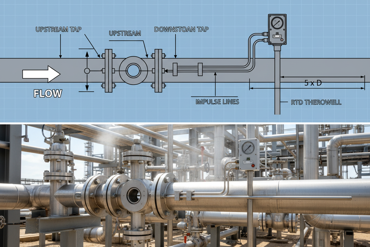
Placing the thermowell downstream eliminates all three failure modes. GE Sensing guidelines specify a minimum downstream distance of 5 pipe diameters (5D) between the downstream tapping and the thermowell leading edge. For steam applications above 30 m/s, engineers extend this to 10D to prevent resonant coupling with the pipe wall.
Installation Procedure and Spacing Rules
- Step 1: Identify the flow direction and mark the upstream and downstream flanges on the orifice carrier ring. Confirm that the orifice plate bevel faces downstream and the upstream tapping is within 0–0.5D of the plate face.
- Step 2: Complete the orifice plate installation and tighten flange bolts to the specified torque value. For ANSI Class 150 flanges in carbon steel service, torque is typically 80–110 Nm in a cross-pattern sequence.
- Step 3: Measure 5D from the downstream tapping point along the pipe centerline. Mark this position as the minimum allowable thermowell entry point.
- Step 4: Select the thermowell immersion depth so that the sensing tip sits at the pipe centerline, corresponding to 50–60% of the inner diameter. For a 100 mm nominal bore pipe, the immersion depth should be 50–60 mm from the pipe wall inner surface.
- Step 5: Install the thermowell using a weld-in socket or flanged boss, depending on process pressure class. For pressures above 40 bar, use a flanged thermowell meeting ASME PTC 19.3 TW-2016 wake frequency calculation requirements.
- Step 6: Insert the Pt100 RTD element into the thermowell and connect using approved extension cable. For a 3-wire Pt100 configuration, verify that lead resistance compensation is enabled in the transmitter — the Yokogawa YTA510 supports this natively for refinery service.
- Step 7: Perform a live check by comparing the transmitter output against a reference thermometer during stable flow. Acceptable deviation is ±0.5°C for custody transfer applications.
Common Field Mistakes and Corrective Actions
Even experienced technicians make consistent errors in orifice-RTD systems. The first common mistake is reversing the installation sequence — placing the thermowell in the upstream straight run to save piping space. The DP transmitter responds to instantaneous differential pressure, not a time-averaged value. Move the thermowell to the downstream side immediately.
The second mistake involves insufficient straight run upstream of the orifice plate itself. ISO 5167 requires 10D–40D upstream straight pipe depending on the beta ratio and the type of fitting upstream. A 90° elbow immediately upstream of a beta-0.6 orifice plate requires 26D of straight run. Engineers often check only the thermowell position and overlook upstream piping compliance entirely.
The third mistake is thermowell insertion depth below centerline. A thermowell that reaches only 40% of the pipe radius measures a boundary-layer-affected temperature, not the bulk fluid temperature. In steam service, this error can exceed 3°C, which directly impacts the density correction applied by the flow computer.
Moreover, GE Panametrics and Yokogawa application engineers both document cases where thermowell vibration caused RTD element fracture within 90 days of commissioning. The solution is to verify the wake frequency ratio (fn/fs) before installation using the ASME PTC 19.3 TW spreadsheet. A ratio above 0.8 requires a stiffer thermowell design or a different insertion depth.
Conclusion and Action Advice
Installing an RTD downstream of an orifice plate is not a layout preference — it is a metering accuracy requirement backed by ISO 5167 and ASME PTC 19.3. Vortex shedding from upstream thermowells corrupts DP readings and can cause structural fatigue. Follow the 5D minimum spacing rule from the downstream tapping, verify immersion depth at pipe centerline, and confirm wake frequency compliance before installation. These steps prevent measurement drift, protect your flow computer’s density compensation, and ensure regulatory compliance for custody transfer metering stations.
Author: Marcus Chen is an industrial automation engineer with over 10 years of experience in PLC, DCS, and control systems.


