

Bridging Allen-Bradley ControlLogix to Yokogawa CENTUM VP DCS via Modbus TCP: Protocol Mapping and Fault Diagnosis
Why Modbus TCP for DCS-to-PLC Integration
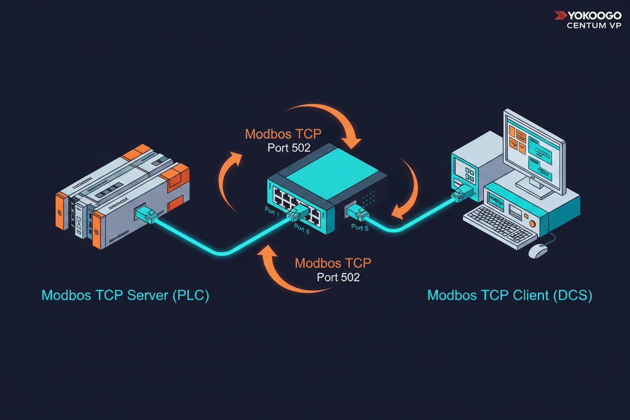
Modbus TCP remains the most widely supported open protocol in industrial automation. It operates over standard Ethernet at the application layer using TCP port 502. Yokogawa CENTUM VP DCS includes a Modbus TCP communication package (ALR121) that enables direct data exchange with third-party PLCs. Allen-Bradley ControlLogix controllers (such as the 1756-L8x series) support Modbus TCP through the 1756-EWEB or 1756-EN2T modules with the Modbus TCP Client/Server AOI (Add-On Instruction).
- The DCS-side communication module acts as the Modbus TCP Client (Master).
- The ControlLogix acts as the Modbus TCP Server (Slave).
This architecture places the DCS in control of polling cycles. The DCS reads process data from PLC holding registers and writes setpoints or commands back to the PLC.
However, mismatched data types and polling timeout configurations cause 80% of integration failures. Understanding the register mapping strategy saves hours of commissioning time.
Step-by-Step Configuration Procedure
Follow this field-proven sequence to establish Modbus TCP communication between CENTUM VP and ControlLogix:
Step 1: Configure the ALR121 communication module in CENTUM VP. Open the System View, navigate to the Vnet/IP communication station, and add a new Modbus TCP subsystem. Set the PLC IP address (e.g., 192.168.10.50) and TCP port (default 502). Define the polling interval. Start with 500ms for general process data. Use 200ms for critical signals like emergency stop status.
Step 2: In the ControlLogix project (Studio 5000 Logix Designer), import the Modbus TCP Server AOI from Rockwell's sample code library. Add the AOI to a periodic task with a 50ms scan rate. Map the internal PLC tags to Modbus holding registers using the AOI configuration array. For a REAL data type (32-bit IEEE 754), allocate two consecutive 16-bit registers. Arrange high-word and low-word in Modbus standard order (big-endian).
Step 3: In CENTUM VP, create PIO (Process Input/Output) tags that correspond to the Modbus register addresses. Use function block 03 (Read Holding Registers) for reading PLC data. Use function block 16 (Write Multiple Registers) for sending commands. Verify each tag's data format: 16-bit integer, 32-bit integer, or 32-bit floating-point.
Step 4: Test the communication using a Modbus diagnostic tool (such as ModScan or Modbus Poll) from an engineering station. Read register 40001 to verify the PLC responds correctly. Check the MBAP header transaction ID increments. A frozen transaction ID indicates the PLC has stopped processing Modbus requests.
Common Modbus TCP Faults Between CENTUM VP and ControlLogix
Three fault patterns appear repeatedly in DCS-to-PLC integrations.
First, the CENTUM VP shows "Communication Timeout" for all tags. Check the physical Ethernet path first. Ping the PLC from the CENTUM VP engineering station. If ping fails, check the VLAN configuration, firewall rules, and switch port settings. Modbus TCP uses TCP port 502 exclusively. Ensure this port is not blocked by any intermediate router or firewall.
Second, some registers read zero while others work. This pattern usually indicates a register offset error. Modbus addressing uses a 0-based offset internally, but many configuration tools display 1-based addresses. Verify that register 40001 in CENTUM VP maps to holding register offset 0 in the ControlLogix AOI.
Third, floating-point values show garbled numbers on the DCS. This occurs when byte order (endianness) differs between systems. The CENTUM VP ALR121 module defaults to big-endian byte order for 32-bit floats. The ControlLogix uses little-endian natively. Configure the byte-swap option in the Modbus TCP communication definition on the CENTUM VP side. Set "Word Swap" to Enabled for 32-bit REAL values.
Optimizing Polling Performance for Large Point Counts
When exchanging more than 500 data points between CENTUM VP and ControlLogix, polling performance becomes critical. The ALR121 module supports up to 125 registers per read request.
- Critical signals (ESD status, fire and gas alarms): 200ms polling
- Process values (temperatures, pressures, flows): 1000ms polling
- Non-critical data (device diagnostics, running hours): 5000ms polling
Pack consecutive registers into single read requests. Reading 100 consecutive registers in one Modbus request is ten times faster than reading 10 separate groups of 10 registers each. This reduces TCP overhead and CENTUM VP communication module loading.
Moreover, implement a watchdog timer in the ControlLogix PLC. Configure a heartbeat register (e.g., 40100) that the PLC increments every second. The CENTUM VP reads this register and compares the value. If the value remains unchanged for 5 seconds, the DCS triggers a "PLC Communication Loss" alarm and holds last good values. This prevents the DCS from acting on stale data during a network outage.
Conclusion & Action Advice
Modbus TCP integration between Yokogawa CENTUM VP and Allen-Bradley ControlLogix requires meticulous register mapping and byte-order alignment. Always verify end-to-end communication with a standalone Modbus tool before commissioning. Configure polling rates based on signal criticality. Implement heartbeat monitoring on both ends.
When troubleshooting, start at the physical layer (ping test), then check the protocol layer (Modbus response codes), and finally examine the application layer (data format and byte order). Document the register map in a shared spreadsheet that both DCS and PLC engineers can access. This single document prevents 90% of integration errors during system upgrades and migrations.
Author: Liu Jianfeng is an industrial automation engineer with over 10 years of experience in PLC, DCS, and control systems. He has commissioned over 30 DCS-to-PLC integration projects across petrochemical and power generation facilities in Asia-Pacific.


