Vortex Flow Meter: Working Principles, Selection Criteria, and Field Commissioning
The Karman Vortex Effect: Physics Behind the Measurement
A vortex flow meter operates on the von Karman vortex shedding principle. When fluid flows past a bluff body placed perpendicular to flow, alternating vortices form on each side downstream. These vortices shed at a frequency directly proportional to fluid velocity. The Strouhal number (St) relates shedding frequency to velocity: f = St × V / d, where f is frequency in Hz, V is velocity in m/s, and d is bluff body width in meters. St remains essentially constant at approximately 0.2 within the valid Reynolds number range, giving the meter its linear output characteristic. The frequency signal requires no density correction for volumetric flow, but mass flow computation requires density compensation via integrated pressure and temperature inputs.
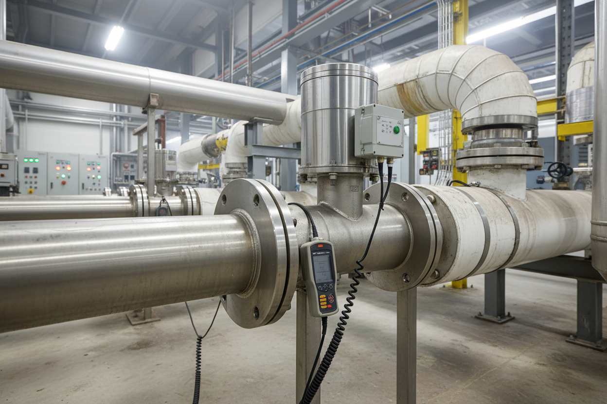
ABB VortexMaster FSV430 series detectors use piezoelectric sensors to detect the oscillating lift force from alternate vortex shedding. Signal conditioning firmware filters pipe vibration noise to isolate genuine vortex signals. For inline electromagnetic flow measurement of conductive liquids as an alternative, the ABB FSM4000 Electromagnetic Flowmeter provides high-accuracy wetted measurement without Reynolds number constraints.
Reynolds Number Constraints and Application Limits
Vortex meters require a minimum Reynolds number (Re) to sustain stable vortex shedding. Below approximately Re = 10,000, the Strouhal number becomes non-constant and measurement accuracy degrades sharply. Therefore, vortex meters suit low-viscosity fluids: water, light hydrocarbon liquids, steam, natural gas, and compressed air. High-viscosity fluids such as heavy fuel oil at elevated viscosity require excessive flow velocity to reach the minimum Re threshold.
Maximum velocity is also constrained. Cavitation damage occurs in liquid applications when vapor pressure is exceeded at the bluff body. Most vortex meters specify a maximum liquid velocity of 7–10 m/s. Gas applications allow higher velocities up to 70 m/s because gas does not cavitate. Steam applications represent the strongest use case for vortex meters — no mechanical moving parts eliminates erosion and bearing wear common in turbine meters.
Meter Selection Criteria and Sizing
- Step 1: Determine the normal operating flow rate (Q_nom), maximum flow rate (Q_max), and minimum flow rate (Q_min). A typical vortex meter turndown ratio is 15:1 to 30:1. If Q_max / Q_min exceeds 30:1, consider a different technology.
- Step 2: Calculate the velocity at Q_max using the pipe bore area. Target velocity between 1.5 m/s and 7 m/s for liquids, or 3 m/s and 60 m/s for gases. Size the meter bore to keep normal operating velocity near the midpoint of this range.
- Step 3: Specify the meter factor (K-factor, pulses per cubic meter). This value is engraved on the meter nameplate. Confirm the K-factor in the transmitter configuration during commissioning. A mismatch between nameplate and configured K-factor causes permanent systematic error. ABB VortexMaster offers 316L stainless steel and Hastelloy C-276 wetted parts; select gasket material to match process chemistry and pressure rating.
Straight Run Requirements and Installation Best Practices
Vortex meters are highly sensitive to upstream flow disturbances. Asymmetric velocity profiles, swirl, and pulsation distort the vortex shedding pattern and degrade accuracy. Standard upstream requirements for ABB VortexMaster:
- Step 1: 15D upstream after a single 90° bend in-plane (where D is nominal pipe diameter).
- Step 2: 25D upstream after two 90° bends out-of-plane. Out-of-plane bends generate swirl that persists over long distances.
- Step 3: 40D upstream after control valves, pumps, or compressors. These devices create severe turbulence profiles.
- Step 4: Minimum 5D downstream in all cases.
- Step 5: Install a flow conditioner upstream when straight run is physically constrained. A tube bundle conditioner typically reduces required upstream straight run from 25D to 10D.
Mount the vortex meter with the electronics housing on the side or top. For vertical pipe installations, ensure flow direction is upward for liquid applications to prevent gas pockets at the bluff body.
Field Commissioning and Output Verification
- Step 1: Confirm K-factor on transmitter nameplate matches the value entered in the flow computer or DCS tag configuration.
- Step 2: Check process connection flange rating and gasket installation for proper seating.
- Step 3: Verify wiring polarity and shield grounding. ABB VortexMaster transmitters output 4–20 mA with HART. Confirm loop impedance is within HART range (250–1100 ohms).
- Step 4: Energize and check the diagnostic display for alarm conditions. ABB VortexMaster firmware reports low-signal warnings when flow drops below minimum detectable velocity.
- Step 5: Open the block valve slowly to approximately 25% and verify output increases proportionally. Sudden full-open commissioning creates hydraulic surge that can damage the piezoelectric sensor.
For Woodward turbine governors using steam flow as a control input, confirm the flow signal scaling matches the expected engineering units at the governor controller card. The Woodward 505 Enhanced Digital Governor Controller and the Woodward 8200-1300 Digital Governor for Steam Turbines accept 4–20 mA analog inputs representing flow as a percentage of maximum. A misconfigured span causes the governor to respond incorrectly to load changes, potentially causing speed oscillation at turbine startup.
Furthermore, perform a zeroing check with flow stopped. The vortex meter should output precisely 4.00 mA. Any residual output above 4.2 mA indicates vibration interference. Identify and isolate mechanical vibration sources within three pipe diameters of the meter body.
Conclusion and Action Advice
Vortex flow meters deliver excellent long-term accuracy in steam, gas, and low-viscosity liquid service with no moving parts to wear. ABB VortexMaster transmitters combined with Woodward turbine control systems represent a proven high-performance steam metering application. Success depends on correct sizing for Reynolds number range, adequate upstream straight run, verified K-factor configuration, and careful commissioning against a known zero reference. Build straight-run compliance into piping design at the P&ID stage to avoid costly retrofits later.
Author: Zhang Haowen is an industrial automation engineer with over 10 years of experience in PLC, DCS, and control systems.


