Temperature Transmitter Calibration: Rosemount 644 and Foundation Fieldbus Configuration
RTD Sensor Selection and Wiring
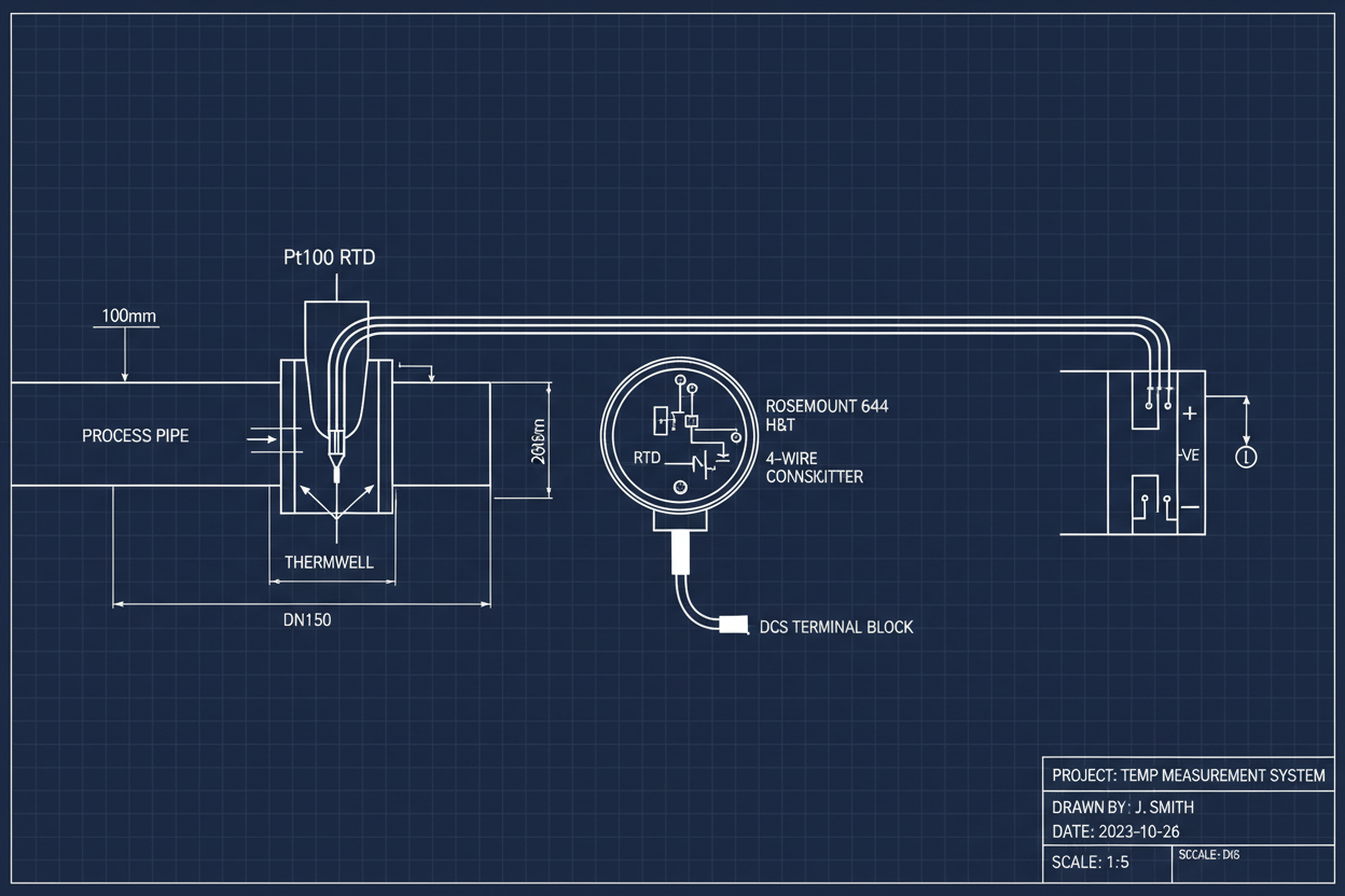
The Pt100 platinum resistance thermometer provides excellent stability with a temperature coefficient of 0.00385 Ω/Ω/°C. Class A sensors offer ±0.15°C accuracy at 0°C, while Class B sensors provide ±0.3°C. Specify Class A for critical control loops and Class B for monitoring applications.
First, select the appropriate wiring configuration. Four-wire RTD connections eliminate lead wire resistance errors entirely — essential for high-accuracy applications. Three-wire configurations compensate for lead resistance when all three wires have identical resistance. Two-wire connections are only acceptable when lead resistance is negligible or compensated mathematically.
Second, verify sensor immersion depth. The sensing element must extend at least ten times the thermowell outer diameter into the process fluid. Insufficient immersion causes stem conduction errors where heat flows along the thermowell wall, measuring a temperature between process and ambient conditions.
Third, check for self-heating effects. Excitation current through the RTD generates heat, raising the element temperature above the process. The Rosemount 644 uses 0.3 mA excitation current, limiting self-heating to approximately 0.1°C in still air. Higher currents in some transmitters can produce errors exceeding 1°C.
Transmitter Calibration and Trim Procedures
Calibrate the Rosemount 644 using a precision resistance source or dry-block calibrator. The transmitter accepts Pt100, Pt1000, Cu10, and various thermocouple types. Configure the sensor type in the device setup menu before beginning calibration.
Perform a five-point calibration: 0%, 25%, 50%, 75%, and 100% of span. For a 0–200°C range with Pt100 sensor, inject resistances corresponding to 0°C (100.00 Ω), 50°C (119.40 Ω), 100°C (138.51 Ω), 150°C (157.33 Ω), and 200°C (175.86 Ω). Record as-found values before adjustment.
Execute sensor trim if errors exceed transmitter specifications. The 644 supports both lower trim and upper trim. Apply the low reference (0°C) and store the reading. Apply the high reference (200°C) and store. The transmitter calculates a two-point linear correction. For non-linear sensors, enable Callendar-Van Dusen equation compensation.
Verify analog output accuracy using a loop calibrator. At 0°C input, the 4–20 mA output should read 4.000 mA ±0.016 mA. At 200°C, output should be 20.000 mA ±0.016 mA. Adjust the analog output trim if readings fall outside tolerance.
Foundation Fieldbus Configuration
Configure Foundation Fieldbus parameters for digital integration. Set the transducer block to match the connected sensor type. Enable sensor diagnostics including open circuit detection, short circuit detection, and measurement validation. For Foundation Fieldbus infrastructure, the Emerson KJ3004X1-BA1 Fieldbus H1 Card and the Fisher Rosemount Redundant H1 Terminal Block KJ3242X1-FA1 provide reliable DeltaV system integration.
Configure the analog input function block with appropriate scaling. Set L_TYPE to Direct for linear temperature display. Set XD_SCALE and OUT_SCALE to match engineering units (degrees Celsius). Configure PV_FTIME for measurement filtering — typically 0.5 seconds for fast loops, 2.0 seconds for noisy applications.
Enable alarm limits in the function block. Set HI_HI_LIM and LO_LO_LIM for safety shutdowns. Set HI_LIM and LO_LIM for process alarms. Configure alarm priorities to integrate with the DCS alarm management system. Enable alarm hysteresis to prevent chattering near setpoints. The Honeywell CC-PFB802 Fieldbus Interface Module and the Allen-Bradley 1788-FBJB6 Foundation Fieldbus Junction Box are available for multi-vendor fieldbus segment builds.
Common Temperature Measurement Errors
- Reading drifts slowly over weeks: Thermowell vibration loosens the sensor connection. Apply anti-seize compound to threads and torque to manufacturer specifications. Check for moisture ingress in the connection head — condensation causes corrosion and resistance changes.
- Step changes in reading: Intermittent connection in the extension cable. Inspect terminal blocks for loose screws. Check for broken strands in multi-strand cable. Replace cables showing insulation damage or conductor corrosion.
- Reading higher than expected: Self-heating from excessive excitation current or poor heat transfer from thermowell. Verify thermowell fill material conducts heat effectively. Ensure process velocity exceeds 0.3 m/s for liquid service to prevent stagnant film formation.
- Thermocouple readings erratic: Cold junction compensation failure. Verify the transmitter ambient temperature sensor functions correctly. Check for electromagnetic interference near high-current cables. Use shielded extension cable with proper grounding.
Calibration Interval and Documentation
- Step 1: Establish calibration intervals based on criticality. Safety-related temperature loops require annual calibration. Monitoring points may extend to three-year intervals based on historical drift data.
- Step 2: Maintain calibration records per ISO 10012. Document as-found and as-left values, environmental conditions, reference standards used, and technician identification.
- Step 3: Trace reference standards to national metrology institutes. Use calibrators with accuracy at least four times better than the transmitter specification.
- Step 4: Calculate measurement uncertainty for each calibration. Include contributions from reference standard, resolution, repeatability, and environmental factors.
- Step 5: Review calibration history to identify drift trends. Increasing drift rates indicate sensor degradation requiring replacement before failure.
- Step 6: Update the maintenance management system with calibration due dates. Generate work orders automatically based on elapsed time since last calibration.
Conclusion and Action Advice
The most frequent temperature measurement errors originate from improper wiring, insufficient immersion, and neglected calibration schedules. Verify wiring configuration matches the transmitter requirements. Confirm thermowell immersion depth during installation. Establish calibration intervals based on historical performance rather than arbitrary time periods. Document all calibrations with complete traceability. A temperature transmitter without calibration history provides unknown measurement uncertainty — unacceptable for process control or safety applications.
Author: Liu Yang is an industrial automation engineer with over 10 years of experience in PLC, DCS, and control systems.


