

VFD-Induced Bearing Currents: Diagnosing Electrical Motor Bearing Damage
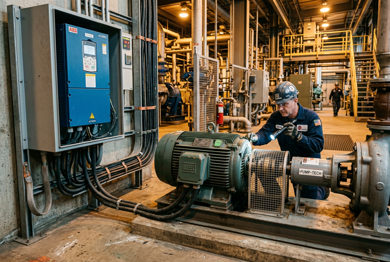
Why Do Bearing Failures Need Electrical Investigation?
Motor bearing failures are often associated with lubrication, alignment, contamination, or excessive mechanical loading. These remain important causes, but they do not explain every repeated failure.
When bearing damage appears after installing or modifying a variable-frequency drive (VFD), engineers should also investigate the electrical system. Fast inverter switching can create high-frequency voltage differences that drive current through unintended paths.
The resulting damage can resemble conventional mechanical wear. Replacing the bearing without investigating the underlying cause may therefore leave the original problem unresolved.
However, a failure occurring after a VFD retrofit does not prove that the drive caused it. Establishing the cause requires evidence from the bearing, motor, drive, cabling, grounding, and operating history.
How Can VFDs Produce Bearing Currents?
VFDs such as the Allen-Bradley 22A-D2P3N104 AC drive regulate motor speed by controlling the frequency and voltage applied to the motor. Pulse-width modulation rapidly switches inverter output devices, producing voltage transitions with high-frequency components.
These electrical conditions can create shaft voltage and unintended current paths through motor bearings.
What are capacitive discharge currents?
Parasitic capacitance within a motor can couple common-mode voltage to the rotor and shaft. When the voltage across a bearing contact exceeds its ability to withstand the electrical stress, a discharge can occur through the rolling contact.
Repeated discharges can produce electrical-discharge-machining damage, including small craters on bearing surfaces.
What are high-frequency circulating currents?
In some motor designs, high-frequency magnetic flux induces voltage between different points along the shaft. This can drive current through the shaft, bearings, and motor frame.
The mechanism depends on motor construction and electrical conditions. Larger motors can be particularly relevant to this type of investigation.
What are shaft-grounding currents?
Voltage differences between the shaft, motor frame, and connected equipment can create another current path. Depending on the installation, the path can involve the coupling and bearings in a connected pump or gearbox.
These mechanisms are distinct, although more than one can occur in the same installation. Engineers should identify the actual current path before selecting a corrective measure.
What Can Bearing Damage Tell You?
Electrical erosion can leave a frosted appearance, small pits, or regularly spaced ridges known as fluting. These patterns can indicate repeated electrical discharge, but visual inspection alone is insufficient for a definitive diagnosis.
| Observation | Possible electrical explanation | Other conditions to investigate |
|---|---|---|
| Fine pitting or frosted raceways | Repeated electrical discharge | Abrasive contamination, corrosion, or other surface damage |
| Regular washboard-like ridges | Progressive electrical erosion | Other periodic wear or indentation patterns |
| Darkened or degraded grease | Possible current-related deterioration | Overheating, oxidation, contamination, or incorrect lubricant |
| Repeated failure after a drive modification | Potential change in high-frequency current paths | Changes in load, alignment, lubrication, or maintenance |
Photograph the bearing before cleaning it. Record the damage location, bearing identification, and motor end. Preserve the removed components when further inspection may be required.
Correlate the physical evidence with operating trends and recent electrical changes. Neither dark grease nor a vibration alarm establishes an electrical cause by itself.
Which Checks Should You Complete Before Replacing Another Bearing?
How do you preserve the failure evidence?
Record the bearing designation and whether it came from the drive end or non-drive end. Photograph the raceways, rolling elements, seals, and lubricant before cleaning.
Collect available vibration trends, operating hours, load conditions, and maintenance records. Also record the VFD model, motor identification, recent parameter changes, and motor-cable information. Drive-side records can include components such as the ABB ACS600 NINT-72C control interface board and the ABB DIS0012 drive interface module.
How do you investigate mechanical and electrical causes?
Inspect lubrication, contamination, bearing fit, shaft condition, housing condition, alignment, and loading. Compare the damage location with the expected mechanical load zone.
At the same time, investigate possible electrical erosion. Mechanical damage and electrical damage can coexist, so the investigation should not force an early choice between them.
What should you check in grounding and cable shielding?
Review the motor protective-earth connection and the complete grounding arrangement. Check shield terminations, bonding joints, corrosion, painted contact surfaces, and changes made during previous maintenance.
Follow the VFD and motor manufacturers' requirements for cable shielding and termination. Where specified, verify the 360-degree bonding arrangement at the motor and drive ends.
A satisfactory DC continuity reading does not establish low impedance at high frequencies. Do not treat a basic continuity test as proof that the high-frequency return path is adequate.
What drive and motor settings should you review?
Record the configured switching or carrier frequency, speed range, operating profile, and relevant drive settings. Compare these details with the approved application configuration and manufacturer recommendations.
Do not change switching frequency or output filtering simply to test a theory. Such changes can affect motor heating, electromagnetic compatibility, drive performance, and other application requirements.
Why examine the complete equipment train?
Include the motor, coupling, gearbox, pump, and driven equipment in the investigation. Potential current paths can extend beyond the motor itself.
Review bonding between connected equipment and check for changes in the mechanical or electrical arrangement. Any corrective measure must preserve protective earthing and applicable safety requirements.
How do you confirm the diagnosis and corrective action?
Use the collected evidence to decide whether specialist measurements are needed. Depending on the suspected mechanism, an appropriately equipped engineer may investigate shaft voltage, high-frequency current paths, or grounding performance.
Consult the motor and drive manufacturers before selecting insulated bearings, shaft-grounding devices, common-mode filters, or other mitigation methods. These measures are not interchangeable and must match the motor and drive application.
How Can You Prevent Repeat Failures?
Effective prevention begins with an installation review rather than a single replacement component. Verify that motor cables, shield terminations, grounding, and drive configuration follow the applicable manufacturer instructions.
For example, ABB's technical guidance on bearing currents discusses appropriate grounding paths, symmetrical motor cables, output filtering, and bearing insulation as possible mitigation measures. The correct combination depends on the drive system and motor design.
Maintain records of the original failure, the selected corrective action, and subsequent operating performance. These records help engineers compare future bearing inspections and identify recurring patterns.
Establish baseline vibration and temperature measurements where appropriate. Combine these trends with maintenance findings and electrical inspection results rather than relying on one indicator. Monitoring devices such as the ABB REM610C55HCMR motor protection relay and the GE Multilin 339 motor protection relay are commonly used to track motor operating conditions.
What Are the Safety and Diagnostic Limitations?
Motor-drive systems can contain hazardous voltages and stored electrical energy. Follow the approved isolation, lockout, discharge, and verification procedures before inspecting electrical connections or removing components.
Live measurements require appropriate instruments, methods, and qualified personnel. Do not bypass protective earth connections or remove required shields while the equipment operates.
Finally, distinguish a suspected mechanism from a confirmed root cause. The strongest conclusion combines physical bearing evidence, electrical findings, operating history, and manufacturer guidance.
Conclusion: Avoiding Repeated Bearing Replacements
Repeated bearing failures in VFD-driven equipment deserve a coordinated electrical and mechanical investigation. Preserve the failed bearing, examine mechanical conditions, review grounding and cable shielding, and verify the drive configuration. Investigate the entire connected equipment train before choosing a corrective measure. Because several failure mechanisms can produce similar symptoms, confirm the diagnosis with appropriate evidence and manufacturer guidance. This process helps maintenance teams avoid repeated replacements and select corrective actions suited to the actual installation.


