Thermocouple Extension and Compensating Cables: Selection, Installation, and Field Fault Prevention
Understanding the Difference: Extension vs. Compensating Cable
The distinction between extension and compensating cables is fundamental. Extension cables use conductor alloys that are identical to the thermocouple wires themselves. Compensating cables use different, lower-cost alloys that approximate the thermocouple’s EMF characteristics only within a limited temperature range, typically 0°C to 200°C.
Extension cables deliver higher accuracy across a wider temperature range. However, they cost more and are stiffer to route through conduit. Compensating cables offer a practical compromise for ambient-temperature cable runs where the cable itself never exceeds 100°C. Use extension cables wherever the cable route passes near furnaces, steam lines, or other heat sources.
Each thermocouple type requires its own matched cable. A Type K thermocouple must pair with a Type KX extension cable or a Type KC compensating cable. Mixing types generates a new junction EMF at the point of connection. This error adds directly to the measured temperature. ABB’s TTF300 temperature transmitters accept input errors quietly — the transmitter simply reports the wrong value without raising an alarm. The ABB DSAI 155A 14-Channel Thermocouple Module and the ABB AI835A Analog Input Module (TC/MV) are both used in 800xA systems for thermocouple signal acquisition.
IEC and ANSI Color Coding Standards
Color coding varies by standard and region. First, understand which standard governs your facility.
Under IEC 60584-3, the positive conductor of a Type K extension cable is green and the negative conductor is white. The overall cable jacket is green. Under ANSI/ASTM E230, the positive conductor is yellow and the negative is red. The overall jacket is yellow.
Honeywell TDC3000 and Experion installations in North American plants follow ANSI color codes. ABB System 800xA plants in European facilities follow IEC codes. Always verify which standard the plant P&ID and instrument index use before ordering cable. A common mistake during plant expansions is mixing IEC and ANSI cables in the same junction box, reversing the polarity of every thermocouple in that group. The ABB AI835 Analog Input Module (TC/MV) supports both IEC and ANSI thermocouple types when configured correctly in the 800xA hardware builder.
Correct Installation Practices
- Step 1: Identify the thermocouple type from the instrument tag and datasheet. Confirm the type before cutting any cable.
- Step 2: Select the correct cable part number using the manufacturer’s cross-reference table. Honeywell and ABB both publish thermocouple cable selection guides for their temperature transmitter product lines.
- Step 3: Route the cable away from high-voltage power cables. Electromagnetic interference from 400V motor feeders induces noise on the millivolt-level thermocouple signal. Maintain a minimum separation of 150 mm, or use a shielded cable and ground the shield at one end only.
- Step 4: Terminate conductors using the correct compensator terminals. Never use standard copper terminal blocks. Install terminal blocks rated for the specific thermocouple type. ABB junction box catalog TB204 and Honeywell type-specific junction heads include matched terminals that prevent inadvertent copper junctions.
- Step 5: Connect the positive conductor to the positive terminal marked with a plus sign or with the conductor color specified in the project wiring diagram. Reversed polarity produces a temperature reading that moves in the opposite direction of the actual process temperature.
- Step 6: Seal cable entries into junction boxes with waterproof glands rated to IP65 or higher. Moisture ingress at terminals creates a galvanic cell between dissimilar metals. This cell adds a small but persistent offset voltage to the thermocouple signal.
Common Fault Modes and How to Identify Them
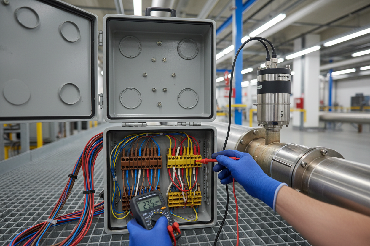
Reversed polarity is the most frequent fault. The temperature reading moves downward when the process temperature rises. Identify this by disconnecting the cable from the transmitter and measuring the open-circuit millivoltage with a calibrated multimeter. A positive temperature above ambient should produce a positive millivoltage when measured correctly. A negative reading confirms polarity reversal.
Grounding faults are the second most common issue. When the cable shield or a conductor contacts plant ground at two points, a ground loop forms. This loop injects 50 Hz or 60 Hz AC noise into the signal. Trend data from the Honeywell Experion historian will show a ripple pattern on the temperature reading. Verify with a millivolt measurement while touching one probe to plant ground. Any reading above 0.1 mV indicates a ground fault.
Therefore, insulation resistance testing should be part of every commissioning and periodic maintenance procedure. Use a 500V megohmmeter. Insulation resistance below 1 MΩ between any conductor and cable shield indicates cable damage that requires replacement.
Conclusion and Action Advice
Thermocouple extension and compensating cables are not interchangeable accessories. They are precision measurement components that require careful selection, installation, and maintenance. Match cable type to thermocouple type on every project, verify color code standards before wiring, and always use CJC-capable transmitters for long runs. Use head-mounted smart transmitters like the Honeywell STT700 or ABB TTF300 to reduce cable-related errors.
Perform insulation resistance checks at commissioning and after any plant modification that touches temperature loops. These steps protect measurement integrity and prevent costly process upsets caused by a misread temperature signal.
Author: Wei Jiaming is an industrial automation engineer with over 10 years of experience in PLC, DCS, and control systems.


