Temperature Measurement Drift in Process Plants: Root Cause Analysis and Correction
Understanding RTD Connection Faults
Temperature measurement drift disrupts PID loops and causes unnecessary energy waste. Plant operators report 2–3 degree Celsius errors that compound over operating shifts. The root cause typically resides in the measurement circuit, not the sensor itself.
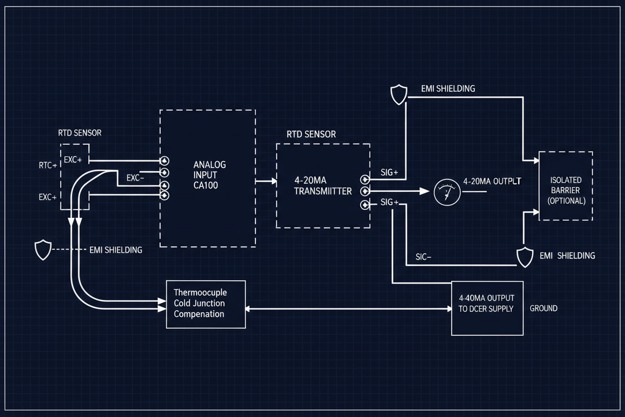
Resistance Temperature Detectors (RTDs) use three-wire or four-wire connections to compensate for lead wire resistance. The Emerson Ovation EPRO EPDG card accepts 3-wire RTD inputs directly. The card measures lead wire resistance and subtracts it from the total reading. However, this compensation assumes equal resistance in all three leads.
- First, verify lead wire gauge consistency. All three leads must use the same AWG wire.
- Second, check connector terminal torque. Loose terminals create intermittent resistance changes.
- Third, inspect wire insulation for chemical attack. Acidic environments attack copper conductors.
- Fourth, measure individual lead resistance at 20°C. Values above 5 ohms per lead indicate undersized wire or corrosion.
The Yokogawa CENTUM VP AAI143 card requires external 250-ohm shunt resistors for 2-wire transmitters. Install precision resistors with 50ppm stability. Cheap carbon resistors drift with temperature changes. This introduces additional measurement error.
Thermocouple Cold Junction Compensation Failure
Thermocouples generate millivolts proportional to temperature differences. The cold junction compensation (CJC) circuit converts these millivolt differences to absolute temperatures. CJC failure produces large constant offsets in readings.
- First, identify the CJC sensor type. Most systems use a thermistor or integrated circuit sensor at the terminal block.
- Second, measure the CJC voltage directly. Use a high-impedance voltmeter. Compare against the expected value at ambient temperature.
- Third, verify the isothermal block thermal coupling. The terminal block must maintain thermal equilibrium.
- Fourth, check for air drafts near the terminal cabinet. Install baffles if ambient temperature fluctuates more than 2 degrees per hour.
The Allen-Bradley 1794-CJC2 Cold Junction Compensation Kit provides automatic CJC for thermocouple inputs. The 1794-IRT8 module reads types J, K, and T thermocouples with built-in CJC. Manual CJC tables allow custom configurations for exotic types R, S, and B.
Transmitter Loop Power Supply Degradation
Two-wire transmitters require 24V DC loop power. Power supply aging reduces output current capacity. The transmitter compensates by reducing sensor excitation. Measurement accuracy suffers.
- First, measure loop voltage at the transmitter terminals under load. The voltage must exceed 12V DC minimum.
- Second, calculate loop resistance. Add transmitter input impedance, cable resistance, and indicator impedance.
- Third, verify the power supply can deliver 4–20mA at maximum loop resistance.
- Fourth, check for diode degradation in loop-powered indicators. Diode forward voltage drop reduces available headroom.
Foxboro I/A Series FBM04 channels provide 4-wire transmitter interface. Channel 1 accepts the 24V supply from an external source. Channel 2 measures the 4–20mA current. This configuration eliminates voltage drop errors from long cable runs. Configure the analog input card scaling in FBM SCP Tool. Set engineering units, damping, and alarming parameters during initial commissioning.
Sensor Calibration Drift Over Operating Cycles
Thermocouples drift from thermal cycling, mechanical vibration, and chemical exposure. Platinum RTDs drift from contamination and handling damage. Scheduled calibration catches drift before it affects product quality.
- First, establish a calibration interval based on sensor type and application severity. Type K thermocouples in reducing atmospheres require 6-month intervals. Platinum RTDs in clean processes tolerate 12-month intervals.
- Second, perform in-situ comparison against reference thermometers. Insert a calibrated reference probe within 10mm of the process sensor.
- Third, record the ambient temperature during calibration. Temperature changes affect reference accuracy.
- Fourth, calculate the combined uncertainty. Include reference thermometer uncertainty, resolution uncertainty, and repeatability uncertainty.
The Allen-Bradley 1794-IRT8 module supports HART protocol for sensor calibration verification. Connect a HART communicator to the 4–20mA loop. Read the sensor calibration data from the transmitter memory. Compare against in-situ verification results.
EMI Interference in Signal Cables
Industrial environments contain substantial electromagnetic interference (EMI). Variable frequency drives, welding equipment, and switching power supplies inject noise into sensor cables. The noise modulates the 4–20mA signal. The DCS sees apparent temperature fluctuations of 5–10 degrees.
- First, route signal cables in dedicated cable trays. Maintain 300mm minimum separation from power cables.
- Second, use shielded twisted pair cables for thermocouple connections. Ground the shield at one end only.
- Third, install ferrite cores on transmitter cables. Common-mode chokes suppress high-frequency noise.
- Fourth, apply RC filtering at the DCS input card. Set the filter time constant to 1–2 seconds for process temperature applications.
The Emerson Ovation system provides software-based filtering on analog inputs. Navigate to the I/O configuration tree. Adjust the Input Filter Time parameter from default 0.5 seconds to 2 seconds. This reduces noise but increases response time. Balance accuracy against control loop performance. The Yokogawa AAI143 analog input module offers similar configurable filtering for CENTUM VP systems.
Conclusion and Action Advice
Temperature measurement errors compound through every stage of the control system. Three actions prevent chronic drift problems.
First, establish baseline measurements during commissioning. Record ambient conditions, cable lengths, and initial calibration data. Use these baselines for future troubleshooting. Second, implement condition-based maintenance for sensors. Replace sensors when drift exceeds 1% of span. Third, maintain detailed calibration records in the CMMS. Track drift trends over time. Predict failure before it affects product quality.
The GE Proficy and Emerson Ovation integration requires consistent engineering units configuration. Verify that both systems use the same temperature scale and decimal precision. Mismatched configurations cause confusion during troubleshooting and shift handover. Reliable hardware such as the Foxboro FBM04 and Yokogawa AAI143 cards form the foundation of accurate temperature measurement in modern process plants.


