

Modbus Protocol Data Storage: Practical Implementation Guide for Schneider and Allen-Bradley Systems
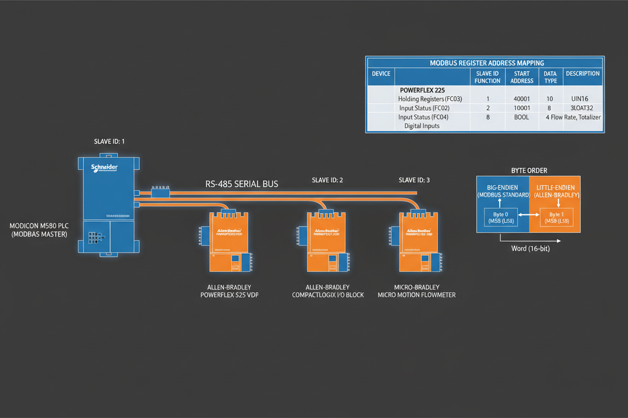
The Pain Point: Why Modbus Data Mapping Causes Commissioning Failures
Automation engineers with extensive experience still encounter Modbus communication failures during system integration. Your Schneider Modicon PLC or Allen-Bradley MicroLogix controller must exchange data with field devices, but addressing differences between manufacturers create persistent problems. Understanding the root causes prevents costly downtime during plant commissioning.
This article addresses practical challenges in Modbus data storage and provides actionable solutions for Schneider and Allen-Bradley platforms. You will learn exact register addressing methods and byte order correction techniques.
Understanding the Four Modbus Data Types
First, recognize the four primary data types in the Modbus standard. Coils occupy address range 00001–09999 and represent single-bit read-write values. Use these for discrete outputs like relay states or valve positions.
Second, discrete inputs occupy range 10001–19999 and represent single-bit read-only values. These typically connect to switches, pushbuttons, or limit switches. Schneider and Allen-Bradley platforms treat these as input status points.
Third, input registers occupy range 30001–39999 and store 16-bit read-only values. Use these for analog inputs from transmitters — for example, the Allen-Bradley 1771-IFE Analog Input Module maps sensor data directly into this register range. The data range spans 0–65535 for unsigned or −32767 to +32767 for signed integers.
Finally, holding registers occupy range 40001–49999 and provide read-write 16-bit storage. Your Schneider PLC uses these for configuration parameters, setpoints, and process values requiring bidirectional communication.
- Coils: 00001–09999, read-write, 1-bit
- Discrete Inputs: 10001–19999, read-only, 1-bit
- Input Registers: 30001–39999, read-only, 16-bit
- Holding Registers: 40001–49999, read-write, 16-bit
Address Offset Correction: Avoiding Common Mistakes
However, different device manufacturers apply different address offsets. This variation causes significant confusion during system integration. Your Schneider Modicon may use 0-based addressing while your Allen-Bradley controller uses 1-based addressing.
Therefore, always verify the addressing convention before configuring communication parameters. The logical address 40065 might map to physical address 64, 65, or 66 depending on the device manufacturer. This three-address variation accounts for most commissioning failures in Modbus networks.
First, check the device documentation for addressing base specification. Second, perform a read test using known values. Third, adjust your PLC mapping accordingly.
Handling 32-Bit Data: Byte Order Considerations
Moreover, floating-point values and 32-bit integers require combining two consecutive 16-bit registers. The byte order within these register pairs critically affects data interpretation. Two primary approaches exist: big-endian and little-endian.
Big-endian storage places the most significant byte (MSB) in the lower address register. Little-endian storage places the least significant byte (LSB) in the lower address register.
If your Schneider controller and Allen-Bradley HMI use different byte orders, you must implement data swapping logic in your PLC program. The swap operation exchanges the contents of the two registers to correct the data interpretation.
- Step 1: Identify data type requiring 32-bit storage
- Step 2: Determine byte order used by each device
- Step 3: Implement swap logic if orders differ
- Step 4: Verify data accuracy using known test values
Master-Slave Configuration: Network Design Best Practices
Finally, design your Modbus network following the master-slave communication model. The master device — typically your Allen-Bradley MicroLogix 1400 or Schneider Modicon PLC — initiates all transactions. Slave devices respond only when addressed.
First, limit the number of slaves on a single network segment to 247 devices maximum. Second, use RS-485 physical layer with proper termination resistors — the Schneider ASMBKT185 MB+ End Connector provides the required 120-ohm termination for Modbus Plus networks. Third, ensure maximum cable length does not exceed 1200 meters at 9600 baud.
Moreover, program your master PLC to implement proper polling sequence and timeout handling. For Ethernet-based Modbus TCP networks, the Schneider TSXETG100 Ethernet Modbus Gateway bridges serial Modbus RTU devices to modern TCP/IP infrastructure. This approach ensures reliable communication even when individual slaves fail.
Conclusion & Action Advice
Successful Modbus integration between Schneider and Allen-Bradley systems requires attention to addressing conventions and byte order. Start by documenting the addressing base for each device. Then implement byte order correction logic for 32-bit data types. Finally, verify all data mappings during commissioning and maintain detailed records for future troubleshooting.
For further reading, refer to the official Modbus specification and the Schneider Electric Modicon support documentation.


