

HIMA Sigma S6 Configuration: Building SIL 3 Safety Logic from Scratch
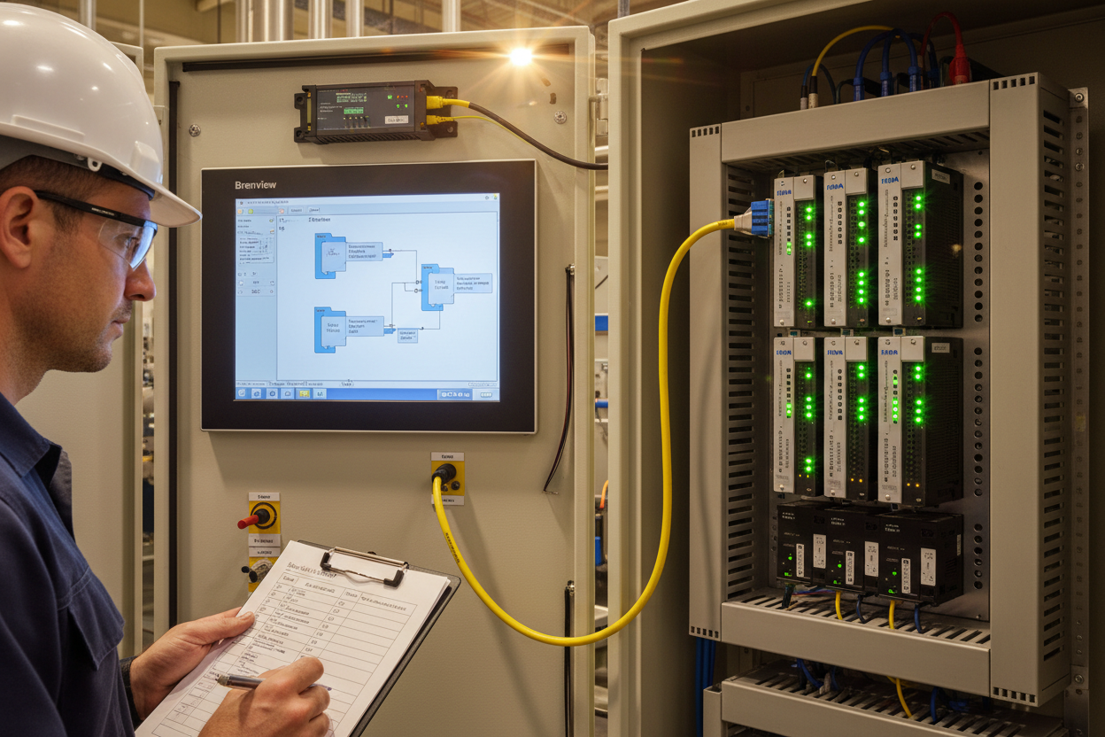
HIMA Sigma S6 Architecture Overview
HIMA Sigma S6 is a modular safety controller designed for high-availability process safety applications. The system uses a 2oo3 (two-out-of-three) voting architecture for critical inputs and a 1oo2D (one-out-of-two with diagnostics) architecture for standard safety functions. The S6 chassis supports up to 16 I/O modules per rack and communicates via PROFIsafe over standard PROFINET infrastructure.
In this guide, we configure a HIMA S6 for a burner management system (BMS) in a 40 MW gas turbine plant. The BMS must achieve SIL 2 per IEC 61511. The example also covers HART transmitter integration through the HIMA HI 645 analog input module.
Brenview HMI Engineering: Project Setup
First, launch Brenview HMI version 6.0 and create a new BMS project. Select the HIMA S6 as the target controller. Define the safety zone structure. The HIMA S6 organizes logic in Function Blocks (FBs). Common blocks include F-Shutdown, F-Motor, F-Valve, and F-Analog.
Second, assign physical I/O addresses. Each I/O module has a unique rack and slot address. The HI 621 digital input module occupies slots 01–04. The HI 641 analog output module occupies slots 11–14. Map each tag name to its physical address in the I/O assignment table.
F-Shutdown Logic Programming in HIMA Sigma S6
The F-Shutdown function block is the core of any HIMA safety program. First, configure the trip inputs. For a gas turbine BMS, the F-Shutdown block monitors flame failure, excessive vibration, oil pressure low, and overspeed. Each input is a voted 2oo3 signal from redundant transmitters.
Second, configure the shutdown response. Set the F-Shutdown block to energize-to-trip (ETT). This means the valve is held open by a 24 V DC energized coil. On a safety trip, the coil de-energizes and the fuel valve closes. This fail-safe design ensures that a loss of power triggers a safe state, which is required for SIL 3 applications.
Step 1: Drag the F-Shutdown FB from the Brenview library onto the function chart canvas.
Step 2: Double-click the FB and configure the voting structure: 2oo3 for critical trips, 1oo2D for non-critical.
Step 3: Set the Proof Test Interval to 8760 hours (annual) per the SRS for SIL 2 classification.
Step 4: Connect digital inputs from the HI 621 module to the F-Shutdown IN1, IN2, and IN3 terminals.
Step 5: Connect the F-Shutdown OUT terminal to the HI 641 analog output channel controlling the fuel valve positioner.
Step 6: Download the compiled safety program to the S6 controller and perform a forced simulation test.
PROFIsafe Communication with ABB AC 800M Controller
HIMA S6 can communicate with the plant DCS over PROFIsafe. In this example, the S6 exchanges trip commands with an ABB AC 800M via a PROFINET backplane. First, configure the HIMA F-Host parameters in the Brenview hardware catalog. Set the PROFIsafe F-Address to match the ABB AC 800M safety module address. Second, define the consumer and producer data exchange areas. The S6 sends a 16-bit safety status word to the DCS, and the DCS sends a 16-bit trip command word to the S6.
Moreover, configure the F-Parameter set in the Brenview PROFIsafe wizard. Key parameters include F_Source_Add (HIMA S6 address), F_Dest_Add (ABB AC 800M address), F_WD_Time (watchdog timeout, typically 100 ms), and F_DataRate (250 kbps for PROFIsafe V2). A watchdog timeout triggers a safe state in the HIMA controller, which is the expected behavior for a communication loss scenario.
SIL 3 Validation and Proof Test Documentation
After completing the configuration, engineers must perform a full functional validation test per IEC 61511 requirements. First, perform a single-channel fault injection test. Force each input channel to a fault state and verify the 2oo3 voted output follows the expected trip logic. Record the trip response time. HIMA Sigma S6 achieves a trip response time of less than 50 ms for digital inputs.
Second, perform an end-to-end calibration check on the HART transmitter channels. Use a HART communicator to inject a 4 mA and 20 mA signal. Verify the corresponding HIMA HI 645 module reads 0% and 100% engineering units. Third, document all validation results in the Safety Validation Report (SVR). The SVR must include test date, test engineer name, test equipment calibration certificates, and pass/fail criteria for each test case.
Conclusion & Action Advice
HIMA Sigma S6 provides a robust SIL 3 capable platform for process safety applications. Brenview configuration software simplifies F-Shutdown logic programming and I/O assignment. Engineers should always follow IEC 61511 lifecycle requirements during FAT and SAT phases. For greenfield projects, consider HIMA S6 with integrated Brenview HMI to reduce interface complexity and improve system diagnostics visibility across the plant.
Author: Li Ming is a senior control systems engineer with 10 years of experience in safety instrumented systems, burner management systems, and turbine protection systems for power generation and oil & gas facilities in China and the Middle East.


