

Emerson Ovation HART Integration: Loop Resistance, Poll Addressing, and Handheld Diagnostics
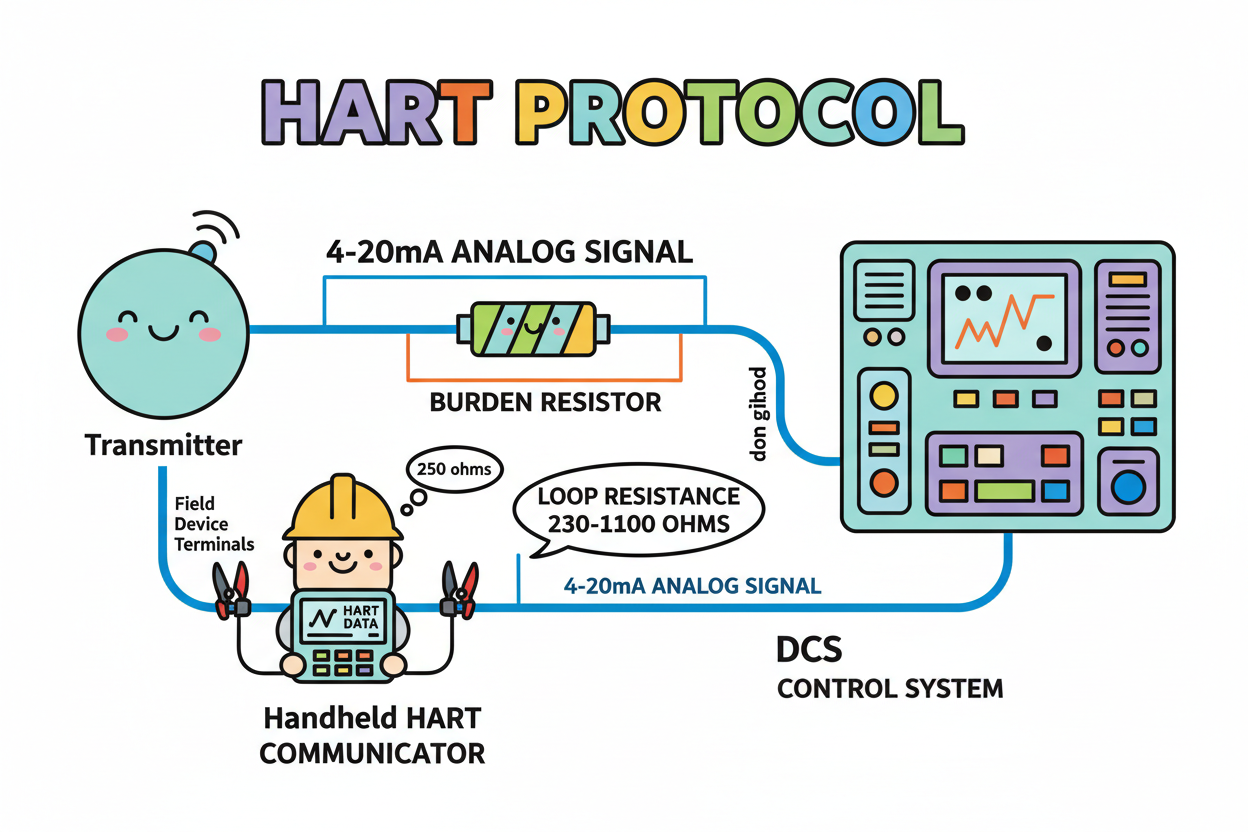
How HART Shares the Analog Loop
HART overlays digital data on a standard 4–20 mA signal using frequency-shift keying (FSK) based on the Bell 202 scheme. Two tones represent bits: 1200 Hz and 2200 Hz. Because the digital average is zero, it does not shift the analog value — the 4–20 mA reading still drives control.
Key rules for every HART loop:
- Loop resistance: Keep total loop resistance between approximately 230 and 1100 ohms. Below 230 ohms, the digital signal collapses and handhelds cannot communicate.
- One device per loop at address zero. Multidrop configurations use addresses 1–15.
- Ground the shield at a single point to avoid noise that corrupts the small digital signal.
In Emerson Ovation, HART variables enter through supported I/O modules — such as the Ovation 5X00058G01 HART Analog Input Module — and surface in AMS Device Manager. Keep Ovation for control views and AMS for asset diagnostics.
Q: How Do Poll Addressing and Multidrop Work?
Each HART device carries a poll address that determines how it communicates on the loop.
- Address 0 — Point-to-point: One device per loop. The analog output is live and drives control. This is the standard mode for most control loops.
- Addresses 1–15 — Multidrop: Multiple transmitters share one pair, each with a unique address. In multidrop, the analog value is meaningless — configure a fixed analog output and rely entirely on digital communication.
A transmitter stuck at address 5 on a point-to-point loop looks dead to the handheld. Always confirm the address matches the wiring style. Primary and secondary masters may coexist — a handheld acts as a temporary secondary master and does not disrupt the primary master polling.
Q: When Should You Use Burst Mode?
Standard HART polling is slow because the master interrogates each device in turn. Burst mode removes the handshake: the device broadcasts one variable continuously without polling. This is ideal for fast flow or pressure readings where update rate matters.
- Burst mode requires address zero — the device needs its own dedicated loop.
- Set the device to burst mode and select the burst variable (typically PV).
- Confirm the analog output range matches the receiving input scaling on the Ovation Fast HART Analog Input Module.
- Verify the reading updates at the process rate, not the poll rate.
Q: How Do You Troubleshoot a Non-Responding HART Device?
A transmitter that will not respond is often misdiagnosed as failed hardware. Run a disciplined checklist first:
- Step 1 — Measure loop current. A steady 4 mA or 20 mA confirms the analog path works. If the analog is healthy, suspect digital comms, not the sensor.
- Step 2 — Verify loop resistance exceeds 230 ohms. Clip a known precision resistor across the transmitter terminals if needed.
- Step 3 — Connect the handheld directly at the device terminals. If it communicates there but not at the cabinet, the fault is wiring or resistance — not the transmitter.
- Step 4 — Check the poll address. Reset to zero for a point-to-point loop and retry.
- Step 5 — Inspect for ground loops and noise. A shield grounded at both ends corrupts the small digital signal.
Also review HART device status and simulation modes in AMS Device Manager. A device left in simulation mode shows a fixed value that masks real process faults.
Q: How Do Device Descriptions (DD) Affect Asset Management?
HART devices identify themselves through a Device Description (DD). Ovation and AMS read this DD to display parameters correctly.
- Keep DD libraries current — a missing or old DD hides newer diagnostic fields.
- Archive every device configuration after commissioning. Restoring a replaced transmitter then takes minutes rather than hours.
- Never rely on factory defaults after a swap — re-verify range, units, damping, and alarm limits on every replacement.
- Use AMS alarm summaries connected to the Ovation Remote I/O Master to trend device health, not just process values.
Conclusion & Action Advice
HART works because it respects both the analog loop and the digital handshake. Keep loop resistance above 230 ohms so the handheld can hear the signal. Match the poll address to your wiring: zero for point-to-point, one to fifteen for multidrop. Reserve burst mode for fast variables on a dedicated loop.
- When a device does not respond, work through the checklist before condemning hardware.
- Keep DD libraries current and back up every transmitter configuration after commissioning.
- Use AMS Device Manager for asset health trending — leave process control to Ovation.
- Ground shields at one point only, and size burden resistors deliberately within the 230–1100 ohm window.
Author: Zhang Weiming is an industrial automation engineer with over 10 years of experience in PLC, DCS, and control systems.


