Allen-Bradley ControlLogix Modbus TCP Setup: RSLogix 5000 Configuration Guide
Q: Why Do I Need Modbus TCP on an Allen-Bradley ControlLogix System?
Allen-Bradley ControlLogix PLCs natively speak EtherNet/IP. However, many field devices — especially Schneider Electric Altivar (ATV) variable frequency drives, Sepam protection relays, and PowerLogic power meters — only support Modbus TCP. This mismatch requires a protocol gateway or embedded Modbus TCP client within the ControlLogix platform.
The recommended approach uses the Allen-Bradley 1756-EN2T EtherNet/IP Communication Bridge Module running a Modbus TCP client layer. For redundant network applications, the Rockwell 1756-EN2TR Dual EtherNet/IP Module provides Device Level Ring (DLR) support alongside Modbus TCP client capability. Alternatively, the Allen-Bradley 1756-EN3TR ControlLogix Ethernet/IP Module supports enhanced security features for Modbus TCP deployments in OT network-segmented environments.
Q: What Hardware and Network Setup Do I Need Before Starting?
- 1756-EN2T or 1756-EN3TR EtherNet/IP module in slot 1 of the ControlLogix chassis.
- Schneider ATV630 VFD connected to the same plant Ethernet network with IP address 192.168.1.20.
- CAT6 shielded cable from EN2T port to the managed switch. Avoid daisy-chaining VFDs directly to the controller module.
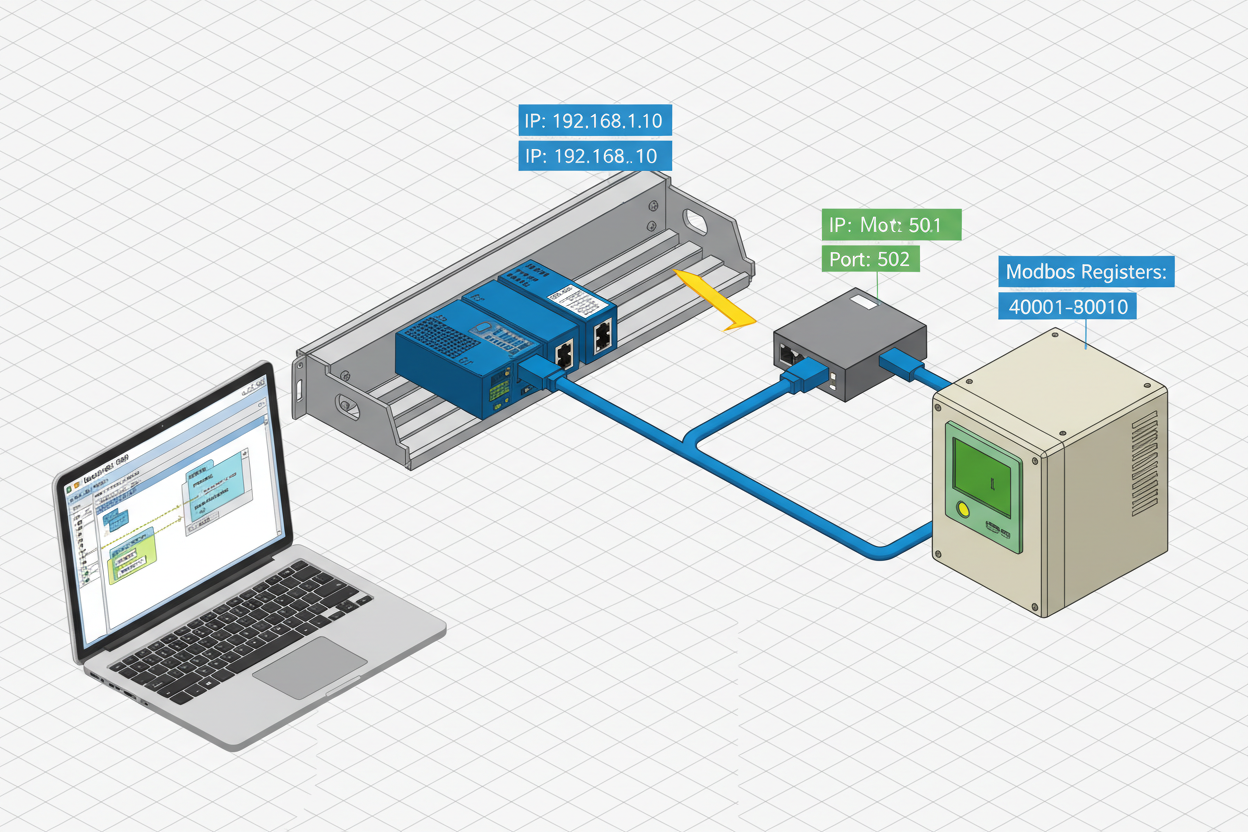
- Network subnet must be consistent: PLC at 192.168.1.10, VFD at 192.168.1.20, gateway at 192.168.1.30.
- Modbus TCP uses port 502. Ensure port 502 is open on the plant firewall for the relevant VLAN.
Q: How Do I Configure the 1756-EN2T Module in RSLogix 5000?
- In the project tree, right-click I/O Configuration → 1756-Backplane → 1756-L85E. Select New Module. Search for “1756-EN2T.”
- Set the module’s IP address to 192.168.1.10. Configure the slot number (typically slot 1) and the chassis size.
- In the module properties, enable Use Unicast Connection for Modbus TCP targets. This reduces network broadcast traffic on large Modbus subnets.
- Set the Requested Packet Interval (RPI) to 100 ms for process-critical registers. For non-critical monitoring, 500 ms is acceptable.
Q: How Do I Map Schneider ATV630 Modbus Registers to ControlLogix Tags?
Add a new Modbus TCP Master (Client) device from the Add-on Profile (AOP) for the EN2T module. Configure the target device: IP address 192.168.1.20, Port 502, Unit ID 255 (standard for Modbus TCP). The ATV630 uses the following key register ranges:
- Register 32001 (CMd): Start/Stop command — write 1 = Run Forward, 6 = Stop.
- Register 32002 (FrS): Frequency reference — write 0–1000 representing 0–100% of max frequency.
- Register 32101 (nSt): Drive status word — read to confirm Run/Stop/Fault state.
- Register 32102 (rFr): Output frequency feedback — read in Hz.
Map Modbus registers to ControlLogix tags: ATV630_CMD_WORD (INT), ATV630_FREQ_REF (INT), ATV630_STATUS (INT), ATV630_FREQ_FB (REAL).
Q: How Do I Write the Modbus TCP Read/Write Logic in RSLogix 5000?
- Create a periodic task (100 ms) to trigger the Modbus request. Use the MSG instruction configured as Modbus Read.
- Read message: Service = Read Holding Registers (Function 03), Source Element = ATV630_FREQ_FB, Number of Elements = 1, Device Address = 192.168.1.20, Modbus Offset = 32101 (subtract 1 from register number — Modbus uses 1-based addressing).
- Write message: Service = Write Multiple Registers (Function 16), Source Element = ATV630_FREQ_REF, Number of Registers = 1, Modbus Offset = 32001.
- Add error handling logic. Monitor the MSG instruction’s .ER (Error) bit. On error, increment an error counter and trigger a MODBUS_FAULT tag. Latch the fault until an operator acknowledge button resets it.
- Configure a watchdog timer. If the Modbus response is not received within 3 scan cycles, declare the VFD offline and trigger a Priority 3 process alarm.
Q: How Do I Verify the Modbus TCP Communication After Commissioning?
- Use the EN2T module’s built-in web diagnostic page at
http://192.168.1.10/diagnostic_modbus.htm. Check the connection status and packet error rate (PER). A PER above 0.1% indicates network issues. - Monitor the ControlLogix tags in RSLogix 5000 online mode. Confirm ATV630_STATUS reflects the actual VFD state (running/stopped/faulted).
- Test the write path by manually entering a frequency reference value and verifying the ATV630’s actual output frequency on its built-in HMI.
- Simulate a network fault by unplugging the VFD Ethernet cable. Confirm the PLC generates a communication fault alarm within 3 RPI cycles.
Important: Never test Modbus write commands on a live process without confirming the VFD is isolated from the driven equipment. A sudden speed command change can cause mechanical damage.
Q: How Do I Troubleshoot Common Modbus TCP Errors?
- Error 16#0001 — Connection refused: Check that the ATV630’s embedded Ethernet port is enabled for Modbus TCP (parameter nMBP = Modbus TCP profile in the VFD parameter menu).
- Error 16#0016 — Invalid register address: Verify the Modbus offset calculation. Subtract 1 from the Modbus register number (Modbus uses 1-based addressing; ControlLogix uses 0-based).
- No response, no error: Confirm the Unit ID in the Modbus message matches the ATV630’s configured Modbus TCP Unit ID (default = 255).
- Intermittent timeouts: Check the Ethernet cable run length. Modbus TCP over copper supports up to 100 m per segment without repeaters.
What Is the Key Action Advice?
Always download the Modbus register map from the device manufacturer’s documentation — register numbers vary between ATV630, ATV320, and Sepam series. Use Modbus function 16 for writes to avoid partial register updates. Never skip the watchdog timer logic — a silent Modbus timeout can leave a VFD running at its last commanded speed without the PLC knowing. Commission the communication fault path before connecting the VFD to the process. Document the complete register map in the PLC project’s tag description field for future maintenance reference. For plants with more than 10 Modbus TCP devices, consider deploying a dedicated Modbus TCP-to-EtherNet/IP gateway module to offload protocol translation from the EN2T processor and improve overall network determinism.
Author: Lin Wang is an industrial automation engineer with over 11 years of experience in Allen-Bradley ControlLogix, Modbus TCP, and Schneider Electric drives across manufacturing and oil & gas facilities in China.


