VFD Harmonic Interference on 4-20mA Instrument Loops: Diagnosis and Suppression with ABB ACS880 and Schneider Altivar 630
How VFDs Inject Noise into Analog Loops
Variable frequency drives switch DC bus voltage at 2 to 16 kHz using IGBT transistors. Each switching event injects high-frequency current into power cables and the surrounding electromagnetic environment. Four coupling mechanisms transfer this energy into adjacent instrument loops.
First, capacitive coupling transfers high-frequency voltage from power cables to instrument cables sharing the same tray. A 300 mm separation reduces capacitive coupling by roughly 20 dB. Second, inductive coupling occurs when long parallel cable runs form a transformer-like geometry. Third, common impedance coupling happens when instrument cable shields share a ground point with the VFD chassis. Fourth, conducted emission propagates through shared trays and corrupts 24 VDC instrument power rails.
ABB ACS880 drives produce switching frequencies between 4 and 16 kHz. The ABB NDCU-11C Drive Control Unit Inverter is representative of the ABB drive platform architecture used in ACS880 series installations. Schneider Altivar 630 drives default to 2.5 kHz with harmonics extending to 100 kHz. Both comply with IEC 61800-3 Category C2. However, C2 compliance does not eliminate analog loop interference — instruments with 250 Ω HART load resistors act as antennas for frequencies below the C2 limit.
Six-Step Field Diagnosis Procedure
Verify that VFD switching is the actual noise source before applying fixes.
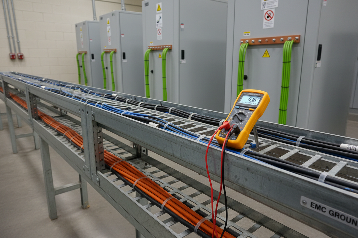
- Step 1: Measure the suspect loop with a Fluke 289 in AC milliamp mode. Normal HART loops show less than 0.02 mA AC ripple. Readings above 0.05 mA indicate external interference.
- Step 2: Shut down the nearest VFD temporarily while monitoring loop current. If AC ripple drops immediately, the VFD is the confirmed source.
- Step 3: Walk the instrument cable from field device to marshalling cabinet. Note all parallel runs within 300 mm of VFD power cables for more than 1 m.
- Step 4: Check shield grounding. The cable shield must connect to ground at one end only — the marshalling cabinet side. Measure shield resistance with a Megger at 500 VDC. Values below 1 MΩ at the field end confirm a double-ground loop that amplifies interference.
- Step 5: Inspect the motor cable shield termination at the ACS880 or Altivar 630 chassis. Use a 360-degree EMC clamp, not a pigtail wire. Pigtail grounding adds 5 to 10 nH inductance and degrades high-frequency shielding by 15 to 20 dB.
- Step 6: Confirm the VFD built-in EMC filter is active. On ACS880, verify filter status in parameter group 95, parameter 95.02. On IT power systems, filter capacitors are sometimes disconnected to prevent earth fault trips — leaving the drive without conducted emission suppression.
Suppression Techniques and Altivar 630 EMC Parameters
Apply corrections from lowest cost to highest disruption. First, install a ferrite split-core common-mode choke with 100 µH impedance at 10 kHz on the instrument cable. This reduces common-mode noise by 30 dB and takes less than 15 minutes per loop. Second, reroute instrument cables at least 300 mm from VFD power cables. Cross power and signal cables at 90 degrees where they must intersect.
Third, add a 3% impedance line reactor to the ACS880 input. This reduces fifth and seventh harmonic currents by 50 to 70% and protects transformer neutral loading. Schneider recommends the VW3A4552 harmonic mitigation module for Altivar 630 drives above 75 kW.
On the Altivar 630, navigate to SoMove software and set control mode parameter MAC to SVC V (Sensorless Vector Control). This reduces current ripple and cuts harmonic emission by approximately 12% versus scalar V/f control. Additionally, reduce switching frequency parameter SFr from 4 kHz to 2 kHz on fixed-speed pump applications. Motor heating increases by 1 to 3°C — verify this is within class F thermal limits. For cable runs exceeding 50 m from drive to motor, enable the dV/dt filter parameter dVFt. This limits voltage rise rate to 500 V/µs and eliminates reflected wave transients that couple into adjacent instrument cables.
Conclusion and Action Advice
VFD harmonic interference on 4–20 mA loops is predictable and solvable. Start with the six-step field diagnosis before spending on hardware. In most cases, correct shield grounding and a ferrite common-mode choke resolves the interference within one hour. For dense VFD environments with SIS loops, invest in cable route separation during the design phase — correction after installation costs ten times more. Always verify ACS880 EMC filter status in parameter 95.02 and Altivar 630 switching frequency before commissioning any drive adjacent to instrument loops.
Author: Chen Hao is an industrial automation engineer with over 10 years of experience in PLC, DCS, and control systems.


