

Industrial Communication Protocols in Oil and Gas: Deploying Modbus TCP and Foundation Fieldbus with Yokogawa CENTUM VP and Emerson DeltaV
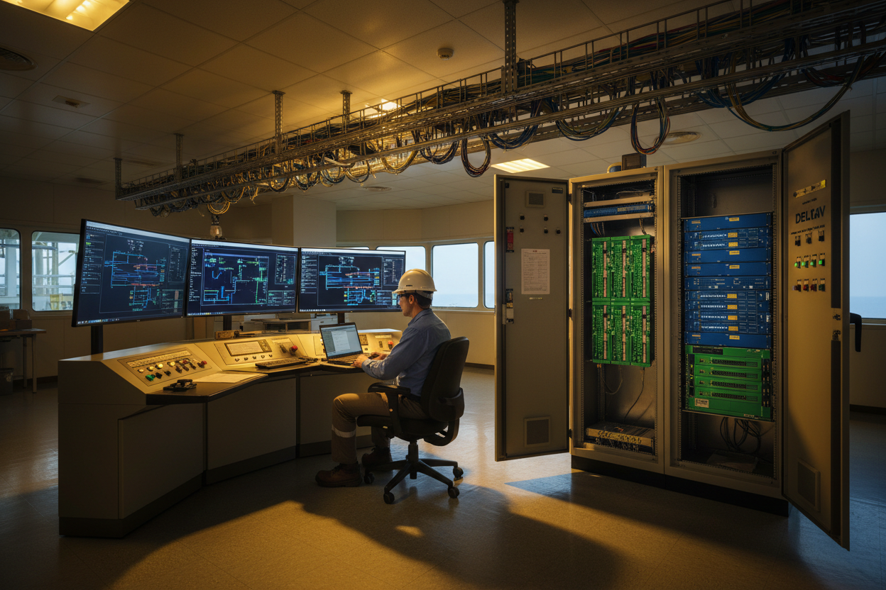
Protocol Selection Framework for Oil and Gas Applications
Oil and gas facilities present unique communication challenges. A single offshore platform may run fifteen different protocols across safety systems, process control, fire and gas detection, and asset management. Selecting the wrong protocol causes integration delays that cost $50,000 to $200,000 per day in deferred production.
First, classify each application by its criticality level. SIL-3 safety functions demand protocols with certified black-channel communication like PROFIsafe over PROFINET. Second, classify by data volume. A compressor health monitoring system streaming 500 tags at 100 ms cycles needs EtherNet/IP or Modbus TCP. A tank gauging system with ten level values updating every 5 seconds runs reliably on Modbus RTU at 9600 bps over RS-485. Moreover, consider the installed base of your DCS. A Yokogawa CENTUM VP system communicates natively on Vnet/IP, which uses standard Ethernet at 1 Gbps, and supports Modbus TCP through the ALR121 communication module. An Emerson DeltaV system uses redundant Ethernet with Modbus TCP via the VIM (Virtual I/O Module) interface and Foundation Fieldbus H1 for field instruments through the DeltaV H1 card.
Step 1: Map every data point to its required update rate. Critical control loops: 100–250 ms. Operator displays: 1–2 seconds. Asset management: 5–30 seconds.
Step 2: Assign protocols based on update rate capability. PROFINET RT and EtherNet/IP handle 1–10 ms. Modbus TCP handles 50–500 ms. Foundation Fieldbus H1 at 31.25 kbps handles 250 ms–1 second per device.
Step 3: Design network segmentation. Keep safety-related traffic on physically separate VLANs. Use managed switches with QoS to prioritize real-time protocols over diagnostic traffic.
Modbus TCP Integration on Yokogawa CENTUM VP
The Yokogawa CENTUM VP DCS offers robust Modbus TCP connectivity through the ALR121 communication module. Each ALR121 supports up to 32 Modbus TCP client connections with a total throughput of 2000 registers per second.
First, configure the ALR121 IP address in the CENTUM VP system view. The module uses a fixed IP on the Vnet/IP control network side and a configurable IP on the field network side. Set the field network IP in the same subnet as the Modbus TCP server devices. Second, define the Modbus communication definition file using the CENTUM VP engineering station. This XML-based file maps Modbus register addresses to CENTUM VP function block data items. The register mapping follows the standard Modbus data model:
- Coil addresses: 00001–09999
- Discrete inputs: 10001–19999
- Input registers: 30001–39999
- Holding registers: 40001–49999
However, many third-party devices use zero-based addressing internally. The ALR121 automatically handles the offset conversion when you set parameter COM_ADDR_BASE to "0" instead of the default "1."
Therefore, always test the register mapping with a Modbus client tool like Modbus Poll before commissioning. Write a known value to holding register 40001 and verify it appears at the correct CENTUM VP PIO data item. A frequent issue involves byte order. The ALR121 defaults to big-endian word order. Yokogawa calls this "Motorola format." If the Modbus server uses little-endian, set parameter COM_BYTE_ORDER to "Intel." Incorrect byte order swaps the high and low words of 32-bit floating-point values, producing nonsensical readings on the operator display.
Foundation Fieldbus H1 Segment Design for Emerson DeltaV
Foundation Fieldbus H1 operates at 31.25 kbps over twisted-pair cable with bus power. Each H1 segment supports up to 16 devices, but practical designs limit to 8–12 devices per segment for voltage drop margin. A standard FF H1 power conditioner delivers 24VDC at 500 mA. Each FF device draws 10–25 mA. A segment with eight Emerson Rosemount 3051S transmitters draws approximately 160 mA, well within the conditioner rating.
First, calculate the segment voltage budget. The FF specification requires 9VDC minimum at the device terminals. Start from the power conditioner output of 24VDC. Subtract cable voltage drop computed as V = I × R, where R is the cable loop resistance. For 1 km of AWG 18 cable at 12.8 ohms per 1000 feet, the loop resistance equals approximately 42 ohms. With a segment current of 160 mA, the voltage drop equals 6.7V. The voltage at the last device equals 17.3V, which exceeds the 9V minimum comfortably.
Moreover, FF H1 uses Manchester-encoded bus power, which combines DC power and digital communication on the same pair. This design simplifies wiring but creates a coupling point for noise. Any 50 Hz or 60 Hz induction from adjacent motor cables couples directly into the FF signal. Use FF-specific shielded twisted-pair cable such as Belden 3076F. Maintain at least 300 mm separation from AC power cables. For parallel runs exceeding 10 meters, increase separation to 600 mm.
Finally, commission each FF segment with the Emerson AMS Device Manager. Run the segment diagnostics tool to measure average noise, peak noise, and signal level for every device. A signal level below 500 mV peak-to-peak indicates a cabling fault, water ingress in a junction box, or a failing device electronics module.
Conclusion & Action Advice
Protocol selection in oil and gas automation is a systems engineering decision with direct impact on project cost and operational reliability. Match the protocol to the application criticality and data rate requirement. Verify byte order configurations on every Modbus TCP link between Yokogawa CENTUM VP and third-party devices. Design Foundation Fieldbus H1 segments with voltage budget calculations, not rule-of-thumb device counts. Commission every segment with a bus analyzer before connecting to the DeltaV H1 card. The protocols are mature and proven. The integration errors that shut down production are entirely preventable with disciplined commissioning.
Author: Wang Jinhua is an industrial automation engineer with over 10 years of experience in PLC, DCS, and control systems.


