PROFINET RT and IRT Network Commissioning: Jitter Diagnosis on Schneider Modicon M580 and ABB AC500
Send clock mismatch causes silent data corruption in PROFINET IRT — here is how to find it before it causes a process trip.
RT vs IRT: Choosing the Right Class for Your Application
PROFINET defines three communication classes. Class A (NRT) uses standard TCP/IP for parameterization and diagnostics. Class B (RT) bypasses TCP/IP for cyclic I/O with typical cycle times of 1–512 ms and a jitter tolerance of ±1 ms. Class C (IRT) reserves dedicated time slots in the Ethernet frame structure, achieving cycle times down to 250 µs with jitter below ±1 µs.
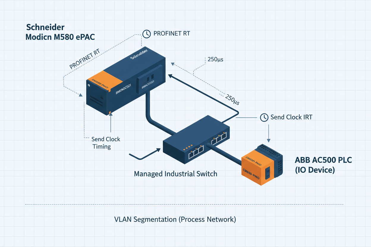
First, confirm your application requirements. Process control applications — flow, pressure, temperature PID loops — rarely need faster than 10 ms cycle time. Use RT Class B with a 10 ms send clock on the Schneider Modicon M580 BMENOC0321 PROFINET module. Motion control and coordinated axis synchronization require IRT Class C with a 1 ms send clock and IRT-capable switches (for example, Siemens Scalance X208IRT or equivalent).
Second, understand that IRT requires hardware-capable switches at every hop. A standard managed switch in an IRT segment breaks the isochronous scheduling immediately. The Schneider Modicon M580 BMENOC0321 module supports RT only; it does not implement IRT scheduling. Therefore, for high-speed motion over PROFINET IRT, deploy a dedicated IRT-capable CPU or coprocessor module.
Moreover, the ABB AC500 CM589-PNIO adapter operates as a PROFINET IO Device only. It cannot function as a controller or I-Device without additional configuration. This is a common setup error: engineers assign the CM589-PNIO as a controller in Unity Pro, which the module does not support. The CM589-PNIO accepts cyclic I/O data from a PROFINET controller at a minimum update time of 1 ms and maximum of 512 ms.
Schneider Modicon M580 PROFINET Configuration Steps
Step 1: In Unity Pro XL, open the DTM Browser. Add the BMENOC0321 Ethernet module to slot 1 of the M580 rack. Assign a static IP address in the range allocated for the PROFINET subnet. Typical setting: 192.168.1.1/24 for the controller, 192.168.1.10–192.168.1.50 for devices.
Step 2: Import the GSDML file for each PROFINET device. Verify the GSDML file version matches the firmware version on the physical device. A GSDML mismatch is the most common commissioning error. The BMENOC0321 validates GSDML schema version at download; an incorrect schema version blocks the network configuration and produces a SERCOS_ERROR 0x8101 in the diagnostic buffer.
Step 3: Configure the send clock. Navigate to BMENOC0321 properties > Network Settings. Set the send clock to 4 ms for standard process I/O. Reduction ratios allow individual devices to run at 4 ms, 8 ms, or 16 ms multiples of the base clock. Set the watchdog multiplier to 3 (watchdog = 3 × send clock = 12 ms). A watchdog timeout generates a diagnostic alarm and sets the process data quality to BAD.
Step 4: Assign PROFINET device names using the PRONETA tool or the Unity Pro Address Assignment wizard. Device names must match the GSDML NameOfStation exactly, including case sensitivity. Mismatched names prevent the device from accepting cyclic I/O and produce a PROFINET ALARM_TYPE 0x0003 (device name mismatch) in the controller diagnostic log.
Step 5: Download the configuration. Verify that the PROFINET LED on the BMENOC0321 shows solid green (BF LED off). A flashing BF LED indicates a bus fault: at least one configured device is not responding within the watchdog interval.
Step 6: In Unity Pro, open the I/O Scanner diagnostic view. Confirm cyclic data exchange status shows RUN for all devices. Check the update counter increments at the configured send clock rate. A static update counter indicates the device is present but not exchanging cyclic data — typically a submodule configuration mismatch.
ABB AC500 CM589-PNIO Adapter Integration
The ABB AC500 CM589-PNIO uses a slot-based I/O mapping architecture. Each CM589-PNIO card presents up to 128 bytes of input data and 128 bytes of output data to the PROFINET controller. Configure the module in Automation Builder 2.x under the Hardware Manager. Select the correct product ID from the GSDML: ABB uses separate GSDML files for CM589-PNIO firmware 1.x and 2.x. Using a version 1.x GSDML on a firmware 2.x module causes diagnostic code 0x0004 (configuration mismatch) and blocks data exchange.
However, note that the CM589-PNIO requires the AC500 CPU to complete its boot sequence before PROFINET communication starts. The module holds data in SUBSTITUTE_ACTIVE mode for up to 10 seconds during CPU startup. Configure the PROFINET controller watchdog to at least 10,000 ms to prevent false fault alarms during startup. After steady-state operation, reduce the watchdog to the normal value of 200–500 ms.
Furthermore, the CM589-PNIO supports PROFINET System Redundancy (S2) when paired with an S-capable PROFINET controller. Two controller connections run simultaneously; the primary controller holds the AR (Application Relationship). On switchover, the backup controller takes the AR within one missed cycle. This feature requires GSDML SystemRedundancy capability flag set to TRUE and a firmware version above 2.4.0 on the CM589-PNIO.
Six-Step Jitter Fault Isolation
Step 1: Connect a laptop with Wireshark to a mirrored switch port on the PROFINET segment. Start a capture filtered on Ethernet type 0x8892 (PROFINET cyclic frames). Sort by time delta between frames.
Step 2: Calculate expected frame interval. For a 4 ms send clock, frames arrive every 4.000 ms. Acceptable jitter for RT is ±1 ms. Any gap above 5 ms or below 3 ms indicates a timing problem — either switch queuing delay or a misconfigured device.
Step 3: Identify the source of jitter. If jitter correlates with broadcast storms, check the VLAN configuration. PROFINET RT traffic must reside on a dedicated VLAN (typically VLAN 10) with EtherNet/IP or standard IP traffic on VLAN 20. Cross-VLAN flooding from a misconfigured trunk port is a frequent root cause.
Step 4: Check switch port duplex settings. PROFINET requires full-duplex, 100 Mbps or 1 Gbps. Auto-negotiate is acceptable on IRT-capable switches but can cause speed mismatch with older device NIC chipsets. Force port speed to 100 Mbps full-duplex on ports connected to the CM589-PNIO and BMENOC0321 if jitter remains above 0.5 ms.
Step 5: Verify cable quality. PROFINET requires Category 5e or better screened twisted-pair (S/FTP) cable per IEC 61784-5-3. Unshielded cable in a high-EMI environment introduces additional jitter. Use a cable tester to verify return loss (RL) above 23 dB at 100 MHz and near-end crosstalk (NEXT) above 40 dB.
Step 6: Review the BMENOC0321 diagnostic buffer in Unity Pro. Navigate to Device List > BMENOC0321 > Diagnostics. Examine PROFINET Alarm records for ALARM_TYPE 0x0005 (synchronization fault) or 0x0001 (I/O data loss). Cross-reference timestamps with Wireshark captures to pinpoint the triggering event.
Conclusion and Action Advice
PROFINET RT and IRT deliver reliable deterministic communication when the network is correctly designed and commissioned. The most common failure modes are GSDML version mismatch, incorrect device name assignment, wrong send clock configuration, and VLAN isolation failures. On Schneider Modicon M580 with BMENOC0321, verify the GSDML schema, set send clock to 4 ms for process control, and configure watchdog at 3× the send clock. For ABB AC500 CM589-PNIO devices, match the GSDML to the firmware version and extend the startup watchdog to 10,000 ms. Use Wireshark captures on a mirrored port to quantify jitter objectively — numbers, not guesswork. A well-configured PROFINET network with proper VLAN segmentation and Cat6a S/FTP cabling sustains less than 0.2 ms jitter under full load.


