Phoenix Contact Axioline Distributed I/O and Bachmann M1 Profibus Integration
The Problem: Expanding I/O Capacity in Legacy Systems
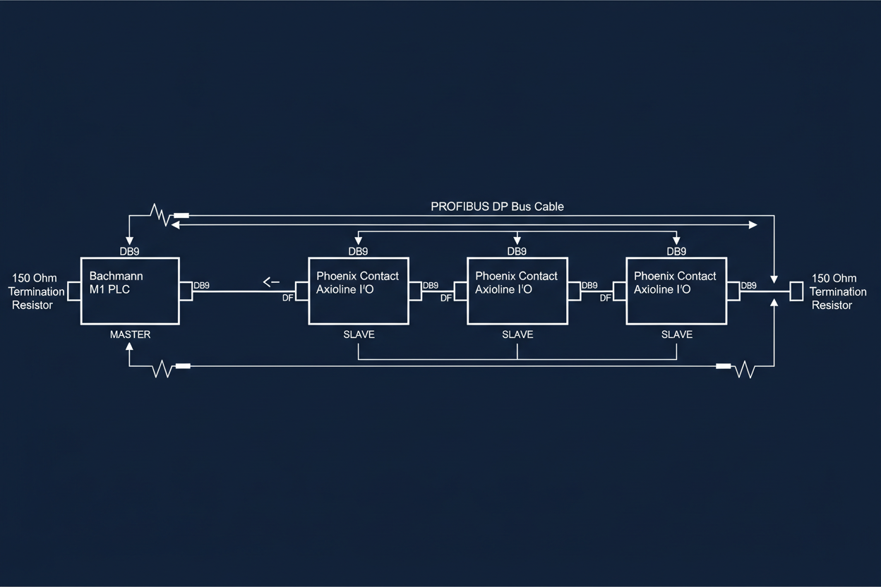
Bachmann M1 controllers offer excellent processing power for power plant automation. However, their native I/O expansion requires proprietary modules that cost premium prices. The solution: integrate Phoenix Contact Axioline distributed I/O via Profibus DP. This approach reduces hardware costs by 40% while maintaining deterministic communication. First, verify the Bachmann M1 has the PROFIBUS master module installed. The Bachmann DPM200 PROFIBUS DP Communication Module supports up to 125 slave devices at 12Mbps and mounts directly on the M1 backplane.
Second, select the correct Axioline master module. The Phoenix Contact AXL F PBProfi Master handles the protocol conversion to Axioline local bus. This module mounts on the DIN rail alongside your Axioline I/O modules. The master module requires external 24V DC power at 500mA. Connect the Profibus cable to the DB9 connector using standard Profibus pin assignments. Pin 3 is RxD/TxD-P (green wire). Pin 8 is RxD/TxD-N (red wire). Shield grounds to pin 1.
Configuring Profibus Network Parameters
Configure the Profibus network using Bachmann Solution Configurator. Add the Phoenix Contact AXL F PBProfi Master to the hardware catalog. Assign it Profibus address 1. Set the bus baudrate to 1.5Mbps for reliable operation over 100-meter distances. Use 1.5Mbps only if your cable length is under 100 meters. For longer runs, reduce to 500kbps. The maximum cable length at 1.5Mbps is 200 meters with proper termination.
Third, add Axioline I/O modules to the station. The AXL F DI8/3 DO8/3 module provides 8 digital inputs and 8 digital outputs. Assign it Profibus address 2. The configuration tool automatically allocates 2 bytes of input data and 2 bytes of output data. Verify these addresses match the M1 program variable mapping. The digital input status word maps to %IX1.0 through %IX1.7. The digital output word maps to %QX2.0 through %QX2.7.
Moreover, configure analog input modules for process monitoring. The AXL F AI4 I U module handles 4-20mA and 0-10V signals. Assign it Profibus address 3. Configure the measurement range in the GSD file. For 4-20mA inputs, set the input filter to 50Hz to reduce noise. The raw value resolution is 12 bits. Scale the engineering units in the M1 program using linear interpolation. Use the formula: Value = (Raw − 6554) / 3276.8 for 4-20mA ranges.
Verifying Communication and Troubleshooting Tips
Use the Bachmann DPM200 diagnostic LEDs to verify Profibus communication. The module has green and red status LEDs. A solid green LED indicates normal operation. Flashing red LED means no slaves are responding. Check the termination resistors at both ends of the Profibus cable. Each end requires a 390-ohm resistor between A and B lines. The resistors are usually built into the last device on the bus.
Fourth, use the Phoenix Contact maintenance software to diagnose Axioline modules. Connect via USB to the AXL F PBProfi Master. The software shows per-module diagnostics including communication errors and supply voltage status. High error counts indicate cable problems or electromagnetic interference. Route the Profibus cable in metal conduit away from VFD motor leads. The minimum separation distance is 300mm for parallel runs longer than 10 meters.
Fifth, perform a cyclic redundancy check on the Profibus telegram. The M1 controller logs all CRC errors with timestamps. A CRC error rate above 0.1% indicates hardware problems. Replace the Profibus cable segment between the erroring slave and its upstream neighbor. Use only Profibus-approved cable with 135-ohm characteristic impedance. Generic Ethernet cable does not meet the electrical specifications.
Conclusion and Action Advice
Therefore, integrate Phoenix Contact Axioline with Bachmann M1 using the PROFIBUS DP protocol for cost-effective I/O expansion. First, install the Bachmann DPM200 PROFIBUS DP module and assign it address 1. Second, mount Axioline master and I/O modules on DIN rail with proper power supply sizing — 500mA minimum for the AXL F PBProfi Master. Third, configure bus parameters in Solution Configurator with correct baudrate for cable length: 1.5Mbps for runs under 100m, 500kbps for longer distances. Fourth, verify termination resistors (390-ohm) at both bus ends. Fifth, use diagnostic LEDs and Phoenix Contact software for fault isolation. Finally, maintain a spare AXL F PBProfi Master module in inventory — the mean time between failures is approximately 50,000 hours, but having a spare minimizes downtime during hardware replacements.


