Machinery Protection: Vibration Probe Installation and Loop Setup
A field engineer's guide to Bently Nevada proximity probe systems — covering gap voltage setup, 4–20 mA loop configuration, and fault diagnosis for rotating equipment.
Why Machinery Protection Needs a Dedicated System
Process control systems monitor flow and pressure. They react to process upsets. Machinery protection systems react to mechanical failure before damage occurs. First, understand the difference. DCS and PLC platforms scan too slowly for machinery protection. They share power and communication with non-critical systems. A vibration trip must execute within 50 milliseconds. Only a dedicated system can guarantee that speed.
Bently Nevada 3500 and Woodward 9905 are the most widely deployed platforms. Both accept proximity probe inputs for radial vibration, axial thrust, and differential expansion. Accurate probe installation and gap voltage setup are the foundation of reliable protection. A 0.5 V DC error in gap voltage can shift the reading by 25 microns.
Proximity Probe Gap Voltage
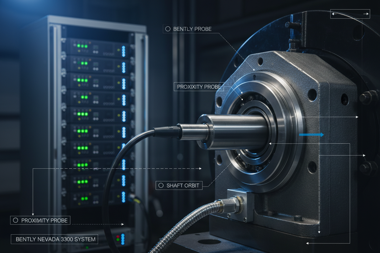
A proximity probe measures shaft displacement using eddy current induction. The probe tip contains a coil driven at 2 MHz. When facing a conductive target, eddy currents reduce the coil impedance. The probe driver converts this into a DC voltage proportional to gap distance.
Set the gap at the midpoint of the linear range. Bently Nevada 3300 8 mm probes have an 8 mm linear range. The nominal output at zero gap is -24 V DC. The optimal gap voltage is -12 V DC, giving equal headroom for shaft motion in both directions. Always verify the probe part number before setting the gap.
Step-by-Step Probe Installation
Step 1: Verify probe resistance and insulation. Measure coil resistance with a four-wire ohmmeter. Bently Nevada 3300 8 mm probes read approximately 6.8 ohms at 20°C. Measure insulation resistance with a 500 V megohmmeter. It must exceed 50 MΩ.
Step 2: Install the probe with correct torque. Use a copper washer for electrical continuity. Over-tightening cracks the ceramic insulator. Under-tightening allows loosening under vibration.
Step 3: Set the gap voltage. Apply -24 V DC to the proximitor. Loosen the locknut. Adjust until the gap reads -12 V DC. Tighten the locknut without rotating the probe. Recheck the voltage. It should not shift by more than 0.05 V.
Step 4: Verify the linear range. Push the shaft in 0.25 mm steps. The voltage should decrease linearly. The measured scale factor should match the certificate within ±5%.
Step 5: Route the extension cable in a separate conduit. Ground the shield at the proximitor end only. Grounding at both ends creates ground loops.
Vibration Transmitter Configuration
Configure alarm setpoints per API 670. Set the alert at 50% of the trip setpoint. Configure a 3-second alert delay and a 1-second trip delay. Configure the 4–20 mA scaling: set 4 mA to 0 microns and 20 mA to the trip setpoint. Program the DCS analog input with the same scaling. A mismatch produces a constant offset error.
Route the 4–20 mA signal on a twisted-pair shielded cable. Power the loop with 24 V DC at 30 mA minimum per transmitter. For cable runs exceeding 500 metres, use a 36 V DC supply to compensate for voltage drop.
Troubleshooting Common Faults
Gap voltage out of range: A reading outside -4 V to -20 V indicates probe contact, probe loss, or short circuit. Probe contact means the shaft is rubbing the probe — shut down immediately. Probe loss reads -24 V; check the extension cable continuity.
Noise on the 4–20 mA signal: A 50 Hz sine wave indicates power frequency interference — check shield grounding. A sawtooth waveform at VFD frequency indicates electromagnetic interference — reroute the cable or install ferrite cores.
Trip relay verification: Inject a signal using a Bently Nevada 130773-1 generator during annual testing. The trip must occur within ±5% of the setpoint. If it fails, check the rack power supply voltage. Replace it if voltage drops below 20 V DC under load.
Conclusion and Action Advice
Machinery protection saves millions in prevented damage, but only when probes are installed correctly. Use a calibrated voltmeter to set the gap. Verify the probe scale factor. Route cables separately from power. Test the trip relays annually. Keep a spare probe for each critical machine. Vibration gives no warnings — be ready the first time.


