

HIMA Safety System Troubleshooting: Module Diagnostics and Fault Isolation
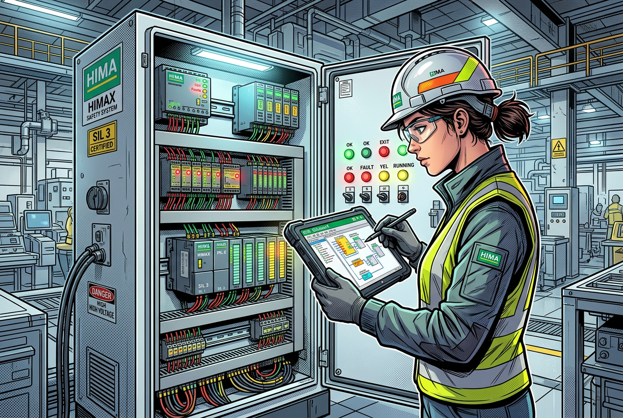
HIMA Safety System Troubleshooting: Module Diagnostics and Fault Isolation
Use controller diagnostics, field checks, and documented procedures to investigate safety-system faults systematically.
Q1: Why must engineers prioritize safety integrity over process availability during HIMA troubleshooting?
HIMA safety-instrumented systems (SIS) protect personnel, high-value assets, and the environment in critical applications. When a fault occurs, troubleshooting must strictly safeguard the safety function before attempting to restore plant availability. Bypassing interlocks, forcing safety logic variables, or executing unverified controller resets to clear alarms violates functional safety standards (IEC 61508 / IEC 61511).
For platforms like the HIMA HIMatrix F35 Safety Controller and HIMax architectures, HIMA provides the SILworX engineering environment for programming, configuration, and online diagnostics. Always verify the current plant state, process dependencies, and trip alarm chronology. Notify operations and certified functional safety personnel before conducting any diagnostic tests that could affect live protective loops.
Q2: How should you isolate safety module faults step-by-step without risking unintended trips?
Systematic fault isolation prevents unnecessary hardware swaps and avoids escalating a minor channel discrepancy into a full process shutdown. Work through these engineering checks:
- Capture Initial Diagnostic Evidence: Record LED status codes, controller error logs, and related SCADA/DCS alarms immediately. Save diagnostic buffers in SILworX before resetting equipment or cycling power.
- Narrow Down the Fault Boundary: Determine whether the abnormality affects a single field channel, an entire I/O rack, a communication gateway, or the main processor. A single sensor wiring fault must not be mistaken for a controller hardware failure.
- Interrogate SILworX System Diagnostics: Open the authorized SILworX project file corresponding to the active runtime version. Match hardware diagnostic codes against the system manual for that specific module and firmware build.
- Inspect Field Circuits and Terminations: Verify wiring continuity, conductor insulation, terminal tightness, power supply voltage, and grounding shielding. Check intermediate interface hardware such as the HIMA X-FTA 002 Field Termination Assembly and backplane interconnects like the HIMA X-CB 008 Connector Board.
- Cross-Compare Symmetrical Channels: Compare the faulty channel with an adjacent healthy channel sharing the same signal type on the module. Look for common wiring duct routing, supply rail loading, or thermal stress.
- Follow Validated Recovery Procedures: Execute recovery strictly according to the platform manual, taking into account redundant channel configurations and hot-swap limitations.
Q3: How do you identify and resolve common HIMA hardware and signal fault patterns?
Safety module diagnostic codes correspond to specific physical failure modes across field and rack equipment:
- Single input reporting wire-break or abnormal value: Inspect field transmitters, barrier isolation, and line-monitoring resistors. On modules like the HIMA F3 DIO 20/8 Digital I/O Module, ensure input filter settings and pulse test configurations match the connected field devices.
- Simultaneous failure across multiple channels: Check the redundant 24V DC field power feed, fuse modules, and common ground return. Multi-channel errors almost always point to power distribution or termination assembly faults rather than individual channel destruction.
- Spurious trips on relay and switching circuits: Test inductive load surge suppressors and check interposing safety units, such as the HIMA H 4007 Safety-Related Switching Amplifier, for contact degradation or excessive back-EMF spikes.
- Communication dropouts or safeethernet faults: Review network switch port statistics, fiber attenuation, subnet routing, and packet jitter on safety communication links.
- Intermittent diagnostic alarms that clear automatically: Investigate loose terminal cage clamps, cable shielding integrity near variable frequency drives (VFDs), or transient supply voltage dips.
Q4: What are the strict rules for HIMA module replacement and configuration management?
Replacing a safety module is a formal management-of-change (MOC) activity. The replacement unit must match the approved Bill of Materials (BOM) in model designation, hardware revision, firmware level, and SIL rating. Even minor sub-version differences can trigger firmware mismatch faults or invalidate safety loop certifications.
Never download logic or parameters copied from another installation without verifying checksums and target hardware compatibility. Always maintain version-controlled backups of the SILworX project, verify CRC signatures, and ensure proper sign-off from designated safety authorities prior to recommissioning.
Q5: What essential steps are required during post-incident closeout and prevention?
- Log comprehensive root-cause analysis findings alongside raw SILworX diagnostic logs.
- Confirm that all temporary forces, simulation variables, and physical jumpers have been completely removed.
- Perform end-to-end loop validation and functional safety proof tests before handing the system back to operations.
- Update the site's maintenance CMMS records, including serial numbers and firmware revisions of replaced hardware.
- Conduct trend analyses during scheduled turnaround windows to catch degrading signals before they cause unscheduled shutdowns.
Summary: What is the golden rule for troubleshooting safety-instrumented systems (SIS)?
Never guess with safety controls. Follow structured, non-invasive diagnostic workflows from the SILworX controller diagnostics outward to the field devices. By preserving fault evidence, validating circuits methodically, and adhering strictly to manufacturer procedures, you ensure plant safety is never compromised during maintenance.


