

HIMA Safety PLC and Yokogawa CENTUM: Implementing 1oo2 and 2oo3 Voting Logic in SIS
What Is Voting Logic in Safety Instrumented Systems?
Voting logic determines how sensors and final elements respond when measurements disagree. In a 1oo2 (one-out-of-two) architecture, either of two sensors can initiate a trip. In a 2oo3 (two-out-of-three) architecture, at least two of three sensors must agree before initiating a trip.
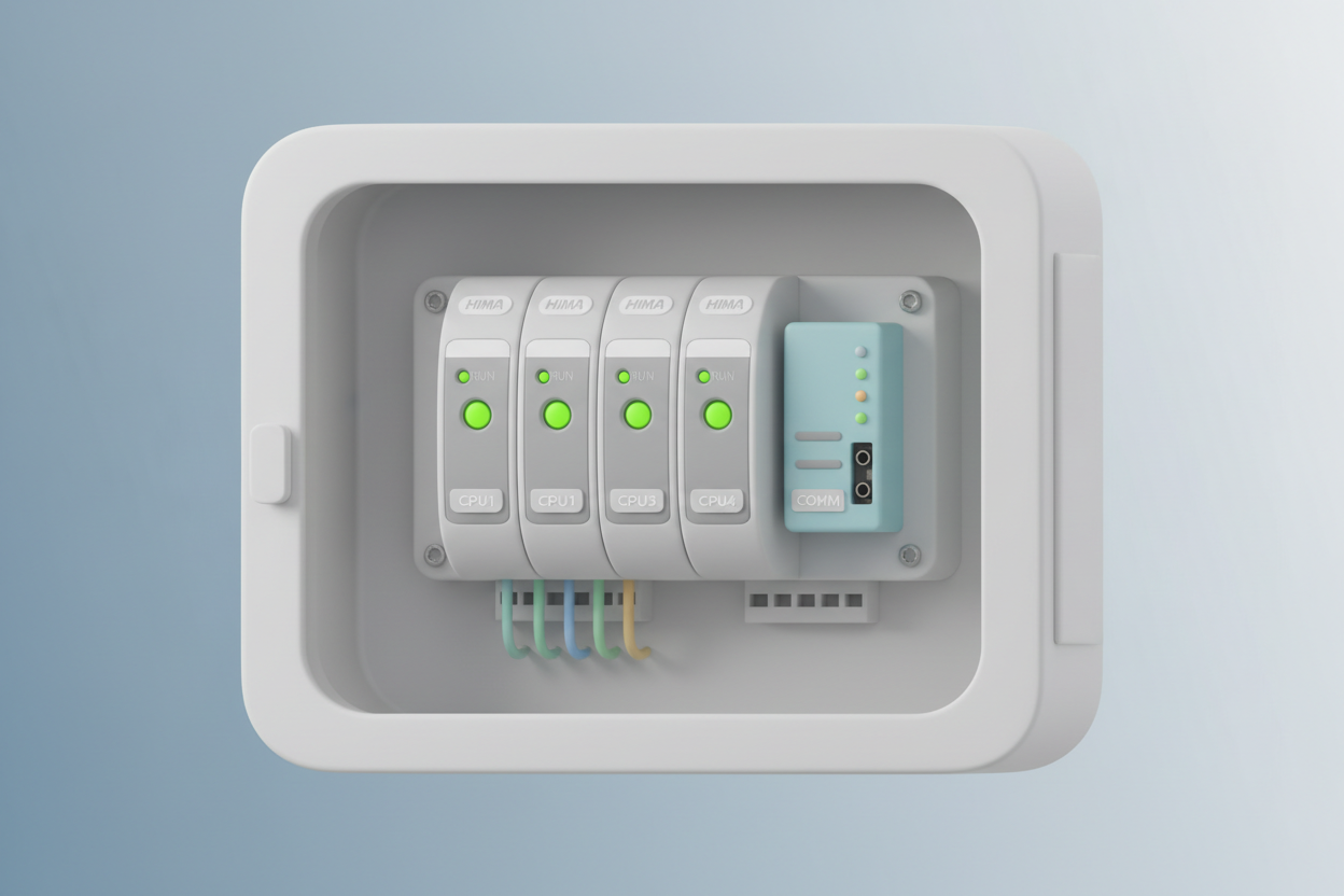
The HIMA Prizm safety controller and Yokogawa CENTUM DCS are frequently deployed together in combined-cycle power plants and refinery heater treatment units. HIMA handles the SIS layer. Yokogawa CENTUM manages the BPCS layer and provides the operator interface via the ProSafe-RS integration. The HIMA CPU Module F8640 is a proven hardware platform for these high-availability SIS architectures.
IEC 61511 Requirements for Voting Architectures
IEC 61511 defines architectural constraints for Safety Instrumented Functions (SIFs). The hardware fault tolerance (HFT) of each channel must match the target SIL. For SIL 2, HFT = 1 requires a minimum of 2 channels (1oo2). For SIL 3, HFT = 2 requires a minimum of 3 channels (2oo3) or two 1oo2 subsystems in parallel.
Moreover, the PFD (probability of failure on demand) must be calculated for the complete voting loop. This includes the transmitters, the Safety PLC processing, and the final elements. The simplified PFD formula for 1oo2 voting is:
PFD₁oo₂ = 2 × λ_DU² × TI² / 3 + λ_DU × MTTR
Where λ_DU is the dangerous undetected failure rate, TI is the proof test interval (typically 1 year), and MTTR is the mean time to restore.
Step-by-Step: Configuring 2oo3 Voting on HIMA Safety PLC
Here is the practical procedure for configuring a 2oo3 pressure trip on a HIMA Prizm controller connected to three pressure transmitters via HART protocol:
- Step 1 — Assign transmitter channels. Wire three 4-20 mA HART transmitters to the HIMA analog input modules (e.g., HIQUAD 4AI). Assign channel addresses PT-101-A, PT-101-B, PT-101-C in the HIMA Engineering Studio.
- Step 2 — Configure the voting block. Insert a 2oo3 voting function block in the Safety PLC logic. Set the input tags to PT-101-A, PT-101-B, PT-101-C. Set the trip setpoint to 150 psi. Set the voting type to "2oo3 MAJORITY".
- Step 3 — Configure the HART communication. Enable HART protocol on each analog input channel. Configure the primary variable (PV) for pressure in psi. Set the update rate to 100 ms for fast response on the safety loop.
- Step 4 — Program the trip output. Route the voting block output to the digital output module driving the EBV solenoid valve. The output must be de-energized (trip) when the voted pressure exceeds 150 psi for more than 500 ms (debounce time). The Yokogawa ADV559-P01 Digital Output (DO) Module is suitable for final element wiring on the CENTUM side of hybrid SIS-BPCS architectures.
- Step 5 — Integrate with Yokogawa CENTUM. Use the Modbus TCP interface to pass the voted trip status to the Yokogawa CENTUM operator station. Confirm the SIS alarm appears on the CENTUM graphic within 1 second of the trip condition. The Yokogawa CENTUM VP AFV10D-S41201 Duplexed Field Control Unit provides the redundant FCU backbone for reliable Modbus TCP gateway operation.
Common Mistakes in SIS Voting Design (ISA-84 / IEC 61511)
ISA-84 and IEC 61511 field experience reveals several recurring design errors. First, using sensors from the same manufacturer in all three voting channels creates a common cause failure. If the sensor firmware has a bug, all three channels fail simultaneously. Therefore, use sensors from two different manufacturers to meet diversity requirements.
Second, routing all three sensor cables through the same conduit introduces common mode failure. Spillers or fire damage to that conduit defeats the redundancy. Route cables on separate cable trays with physical separation of at least 300 mm.
Third, failing to perform annual proof tests destroys the PFD calculation. If the proof test interval (TI) is extended from 1 year to 3 years without re-calculating PFD, the system may no longer meet the target SIL.
Common Cause Failure in 2oo3 Architectures
Common Cause Failure (CCF) is the primary weakness of voting architectures. CCF occurs when a single event simultaneously degrades multiple channels. Temperature, humidity, vibration, and electromagnetic interference are typical CCF initiators.
To reduce CCF, follow these field practices. First, install sensors in separate enclosures or at physically separated locations on the process vessel. Second, use separate power supplies for each analog input channel. The Yokogawa SPW481 AC Power Supply Module supports dedicated per-channel power distribution in CENTUM I/O cabinets. Third, perform annual diversity audits. Confirm that the three sensors use different firmware versions or different hardware revisions.
When a 2oo3 system is properly designed, its PFD stays below 0.001 (SIL 3) even with a CCF factor of 5% included. Without CCF mitigation, the effective PFD can degrade by a factor of 3, risking SIL non-compliance.
Conclusion and Action Advice
Voting logic on HIMA Safety PLC integrated with Yokogawa CENTUM provides robust, SIL-certified protection for critical process units. However, the architecture is only as strong as its weakest design detail. Common cause failure, cable routing, and proof test discipline are the three areas where field teams most frequently fall short.
Action advice: Schedule a voting logic review with your Safety Instrumented System (SIS) engineering team this quarter. Verify that all 2oo3 sensor channels are physically separated and on separate power supplies. If any channel shares a conduit or power rail, issue a punch list item before the next turnaround.


