Emerson Ovation DCS + Woodward 505: Profibus DP Configuration for Steam Turbine Control
Q: Why Is Profibus DP the Preferred Protocol for Ovation-to-Woodward Integration?
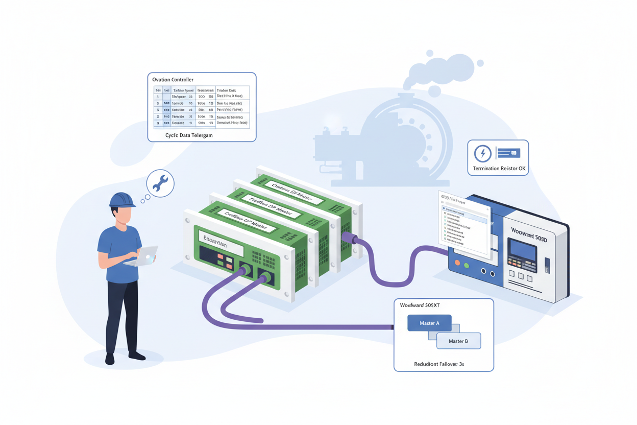
Steam turbine generator sets form the backbone of many power plants. The Woodward 505 digital governor manages turbine speed, load, and extraction pressure with sub-millisecond precision. The Emerson Ovation DCS provides plant-wide supervision, alarming, and historian functions. Profibus DP operates at up to 12 Mbps over RS-485 physical layer, making it the field-proven choice for this critical link.
The Woodward 505 Enhanced Digital Governor Controller (9907-1182) and Woodward 505 Turbine Control Governor Enhanced Digital (9907-1183) both act as Profibus DP slaves, scanned by the Ovation DCS Profibus DP master card at configurable rates. A misconfigured GSD file causes intermittent communication dropouts that cascade into turbine load rejection events — GSD version verification must be Step Zero before any Profibus commissioning.
Q: How Do I Configure Profibus DP Step by Step?
- Step 1 — Import and Verify the Woodward GSD File: Download the 505XT GSD file “WOOD0A6F.GSD” from the Woodward website. In Ovation Developer Studio, navigate to I/O Builder → Profibus → Import GSD. Open the GSD file in Notepad++ and search for “GSD_Revision” and “Hardware_Release”. Confirm Hardware_Release matches the firmware sticker on the Woodward 505XT CPU board. Firmware v5.02 requires Hardware_Release=5. If the GSD file says Hardware_Release=3, contact Woodward for the updated file.
- Step 2 — Configure the Profibus DP Master Parameters: In Ovation Developer Studio, select the PDP01 module in the controller rack. Set Baud Rate to 1.5 Mbps for cable runs under 200 metres. Configure Target Rotation Time (Ttr) to 20 ms. Set Slot Time (Tsl) to 300 t_bit. Assign station address 3 to the Woodward 505XT slave. Enable Watchdog Control with Watchdog Factor 1 = 3 and Watchdog Factor 2 = 5 — establishing a 60 ms watchdog timeout.
- Step 3 — Map the Cyclic Data Telegram: Configure Input Data = 32 bytes and Output Data = 32 bytes. Map the first 4 bytes of input data to Turbine Speed (REAL, IEEE 754 float). Map bytes 5–8 to Turbine Load (REAL). Map byte 9 as bit-packed status word where bit 0 = Shutdown, bit 1 = Alarm, bit 2 = Speed Control Active. Ovation uses Motorola (Big-Endian) byte order — Woodward 505XT Profibus also uses Big-Endian, so no byte swap is needed.
- Step 4 — Test Redundancy Switching: Configure both PDP01 modules with identical parameters and different station addresses (typically 0 and 1). Force a failover by disabling the primary PDP01 module from Ovation Developer Studio. Verify the Woodward 505XT maintains Data Exchange state with zero dropout. The transition must complete within 500 ms. Use the Ovation SOE recorder to timestamp the exact failover duration.
- Step 5 — Configure HART Device Integration on the Turbine Skid: Connect HART-enabled pressure transmitters to the Emerson Ovation 5X00106G01 Analog Input Module Fast HART. In Ovation Developer Studio, assign each HART device a unique polling address (0–15). Enable HART secondary variable (SV) polling to read device temperature alongside the primary PV. Set the HART update rate to 500 ms for fast-response pressure loops.
- Step 6 — Build the Turbine Control Faceplate: In Ovation Graphics Builder, create a turbine control overview display. Add a numeric display object bound to the Woodward speed PV (bytes 1–4 of Profibus input). Add a horizontal bar graph for turbine load (0–110% scale). Add alarm indicators for Shutdown and Alarm status bits. Test the faceplate with simulated data from the Ovation Virtual Controller before connecting to the live Woodward unit.
Q: What Are the Top 5 Commissioning Pitfalls and How Do I Fix Them?
- GSD version mismatch: Firmware v4.08 with a v4.12 GSD file corrupts the cyclic data telegram. The Ovation Controller logs error 0xE001 “Profibus Slave Data Inconsistent” while the Woodward 505 front panel shows “DP Online”. Always audit GSD version before commissioning.
- Missing termination resistor: Measure DC voltage across Profibus connector pins 3 and 8 — a properly terminated bus reads 0.9–1.1 VDC. A missing terminator at the Woodward end causes signal reflections.
- Ground loops on cable shield: Ground the Profibus cable shield at exactly one point — the Ovation cabinet ground bus. Multiple ground points create 50/60 Hz noise on the RS-485 differential pair.
- Hot-swapping the Profibus connector: Never hot-swap the Profibus DP connector on a live Woodward 505XT. The voltage transient can latch up the Woodward’s Profibus ASIC, requiring a full controller power cycle.
- Parameterization timeout: Increase the Ovation PDP01 module parameter Min_Slave_Interval from default 1 (100 µs) to 5 (500 µs). This allows the Woodward Profibus stack adequate time to acknowledge each parameterization telegram.
What Is the Key Action Advice?
Start every commissioning with a GSD version audit. Configure redundant masters for turbine applications where a communication failure would cause turbine trip. Document all Profibus parameters in the site I/O database and lock the configuration with Ovation Security Administrator. Schedule an annual Profibus physical layer health check using a Profibus tester such as the Softing PB-T3 to measure signal quality, reflections, and noise margin.
Author: Li Xiaofeng is an industrial automation engineer with over 10 years of experience in PLC, DCS, and control systems. He has commissioned over 30 turbine control systems integrating Emerson Ovation DCS with Woodward, GE, and Triconex turbine governors across Southeast Asian power plants.


