Emerson DeltaV SIS Hot Standby Switchover and Scan Time Optimization
Why Hot Standby Matters in SIS Architectures
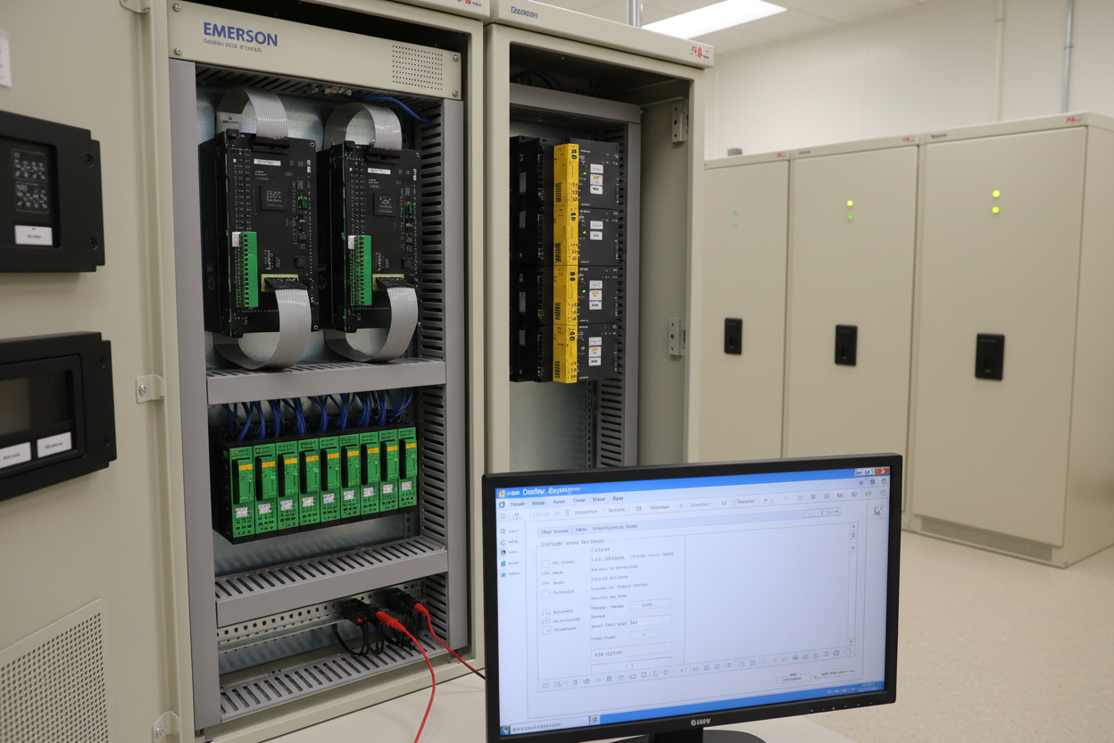
A safety instrumented system must respond within its defined process safety time (PST). The Emerson DeltaV SIS SLS 1508 logic solver uses 1oo2D hardware architecture, pairing a primary processor with a hot-standby processor. Both processors run identical logic continuously. Switchover occurs in under 100 ms, meeting IEC 61511 Clause 11.9 availability requirements for SIL 2 loops.
However, poor configuration leads to nuisance switchovers that disrupt control and trigger spurious alarms. The root cause is usually a misconfigured watchdog timer or excessive scan time. Misaligned heartbeat intervals between a Honeywell Safety Manager SC and a DeltaV SIS in the same ESD cabinet can cause false diagnostics mismatch alarms within weeks of commissioning.
SLS 1508 Dual-Processor Synchronization Architecture
The SLS 1508 contains two CPUs: CPU-A (primary) and CPU-B (standby). They share a synchronization bus operating at 100 Mbps. Every scan cycle, CPU-A writes its I/O table to CPU-B. CPU-B compares the incoming data against its own scan result. A mismatch counter increments on any deviation. The watchdog triggers a switchover when the counter exceeds the configurable threshold.
Key parameters to verify during commissioning:
- Watchdog timeout: default 500 ms, minimum 200 ms for SIL 2 PST < 2 s
- Synchronization mismatch threshold: default 3 consecutive mismatches before switchover
- CPU-B scan offset: must not exceed 10 ms relative to CPU-A
- Memory checksum interval: every 60 s for application code integrity verification
Access these parameters in DeltaV Explorer under SLS Controller Properties. Set the watchdog to 400 ms when PST is 1.5 s. This provides a 1.1 s margin after fault detection before the final element must respond.
Scan Time Budget and IEC 61511 Compliance
IEC 61511 Clause 11.7.5 requires the logic solver scan time to be less than or equal to one-tenth of the PST. For a PST of 2 s, the maximum scan time is 200 ms. The DeltaV SIS typically runs at 100 ms for SIL 2 and 250 ms for SIL 1. Verify the actual scan time in DeltaV Diagnostics under Controller Performance.
- Step 1: Open DeltaV Explorer. Navigate to SLS Controller → Module Properties → Scan Statistics.
- Step 2: Record the maximum scan time over a 24-hour period. Include shift-change peaks.
- Step 3: Identify function blocks consuming more than 5 ms individually. These are candidates for separation.
- Step 4: Move non-safety logic blocks (e.g., cause-and-effect matrix calculation helpers) to a DeltaV CHARM I/O controller instead.
- Step 5: Re-check scan time after redistribution. Confirm it remains below 180 ms with a 10% margin.
Switchover Fault Isolation: Five-Step Procedure
Nuisance switchovers generate a DeltaV Event Chronicle entry at severity level 10. Use the following procedure to isolate the root cause:
- Step 1: Export the Event Chronicle for the 30 minutes preceding the switchover. Filter by source SLS Controller. Look for mismatch count increments and CPU temperature alarms.
- Step 2: Check 24 VDC supply rail voltage at the SLS 1508 backplane terminals P1 and P2. Acceptable range is 21.6–26.4 VDC. Voltage below 22 VDC causes synchronization bus errors.
- Step 3: Verify the synchronization bus cable between the two CPU cards. DeltaV SIS uses a proprietary ribbon cable. Inspect for bent pins at the card edge connector. Replace if resistance between pin 1 and pin 16 exceeds 5 Ω.
- Step 4: Review the I/O mismatch log. A specific input channel appearing repeatedly indicates a failing field device or loose termination. Check the associated DIN rail terminal block for oxidation.
- Step 5: Confirm firmware revision on both CPUs matches. Navigate to SLS Controller Properties → Diagnostics → Firmware Version. Mismatched firmware versions cause continuous low-level mismatches at 1–2 per minute.
PFDavg Impact of Extended Scan Times
A scan time exceeding the IEC 61511 budget does not cause an immediate trip. However, it inflates the diagnostic coverage credit claimed in the SIL verification calculation. Emerson rates the SLS 1508 diagnostic coverage at 99% (DC = 0.99) only when the scan time stays within the rated value. If scan time exceeds 200 ms for a SIL 2 loop with a 1-year proof test interval (Ti = 8,760 h) and λDU = 2×10⁻⁶/h, the PFDavg rises from 0.0088 to approximately 0.0115 — breaching the SIL 2 upper limit of 0.01.
The Honeywell Safety Manager SC installations often run beside DeltaV SIS in the same ESD cabinet. The Safety Manager uses a 200 ms task cycle by default. Ensure the two systems share the same NTP time source — use a stratum 1 GPS-disciplined clock on the OT network. A time offset above 50 ms between the two SIS systems causes sequence-of-events logs to misorder initiating causes and final element responses.
Conclusion and Action Advice
Emerson DeltaV SIS hot standby performance depends on three factors: watchdog timer alignment, scan time budget compliance, and synchronization bus integrity. Start with a 24-hour scan time baseline before final acceptance. Confirm the mismatch threshold and firmware revision are identical on both CPUs. Redistribute function blocks if CPU utilization exceeds 80%. Validate the 24 VDC supply at the backplane terminals. These steps protect your SIL 2 PFDavg calculation and prevent nuisance switchovers in production. Document every parameter change with as-found and as-left records per IEC 61511 Clause 16.3.
Author: Chen Hao is an industrial automation engineer with over 10 years of experience in PLC, DCS, and control systems.


