Bachmann M1 Controller Hot Standby Redundancy Configuration and Modbus TCP Commissioning with Schneider Modicon Quantum
Hot Standby Redundancy Architecture in Bachmann M1
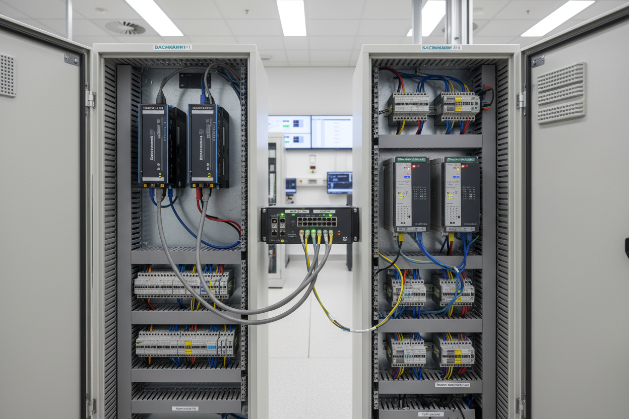
Bachmann M1 systems achieve controller redundancy via the MX213 hot-standby module. This module synchronizes the primary and standby CPUs over a dedicated synchronization link. First, mount the MX213 in slot 0 of the M1 rack. Second, connect the SYNC cable between the two rack assemblies (maximum 10 meters). Moreover, the synchronization runs at 2 Mbit/s using a proprietary protocol that transfers I/O image data, retentive variables, and system status. However, if the SYNC cable fails, the standby CPU continues running independently without taking over. The host system must handle this mode transition gracefully.
The synchronization cycle time defaults to 10 ms. Engineers can adjust this parameter via the Bachmann M1 Studio software under the MX213 configuration tab. A shorter cycle reduces the data loss window during switchover. For high-speed applications, set the cycle to 5 ms. The M1 monitors the heartbeat between primary and standby using the HOT_STBY_OK system variable. If this variable drops to zero for more than 500 ms, the standby initiates a bumpless transfer to Primary role. Bachmann M1 supports up to 31 stations on the M1 System Bus.
Schneider Modicon Quantum Hot Standby Configuration
Schneider Modicon Quantum 140CPU 67160 provides native hot-standby support with the CEX-Bus backplane. The primary and standby CPUs share a common set of outputs via the diode-OR architecture. First, install the 140CPU 67160 in slots 01 and 02 of rack A. Second, configure the Hot Standby pair using Unity Pro XL software. Moreover, set the SYNC timeout to 50 ms in the CPU configuration tab. A value below 50 ms risks false switchovers during network traffic spikes. The Schneider Modicon 140CHS11000 S911 Hot Standby Module provides the hardware synchronization interface for Quantum hot-standby pairs.
The Quantum Hot Standby requires matching firmware versions on both CPUs. Schneider recommends using the same firmware build to avoid synchronization mismatches during bumpless transfer. Quantum outputs use the diode-OR scheme to combine primary and standby signals. Each output channel includes a Schottky diode that prevents cross-feeding between the two CPU sources. The forward voltage drop across the diode must remain below 0.4V to ensure sufficient output voltage at the field device.
Modbus TCP Communication Between Bachmann M1 and Schneider Modicon Quantum
Cross-vendor communication between Bachmann M1 and Schneider Quantum commonly uses Modbus TCP. The Bachmann M1 Ethernet interface module (MX209) exposes Modbus TCP server functionality at port 502. The Schneider Quantum 140CPU 67160 acts as the Modbus TCP client (master). First, assign static IP addresses to both controllers on the same VLAN. Second, configure the MX209 Modbus server with the target IP of the Quantum CPU.
- Step 1: In Bachmann M1 Studio, add the MODBUS_TCP_SERVER function block to the application. Assign a start address for holding registers (e.g., 40001 for the first register).
- Step 2: Map M1 process variables to Modbus holding registers. Use FC03 (Read Holding Registers) and FC16 (Write Multiple Registers) for bidirectional data exchange.
- Step 3: In Unity Pro XL, configure the Quantum as Modbus TCP client. Add an EFB (Elementary Function Block) channel using the MODBUS_TCP_CLIENT block. Enter the M1 IP address, port 502, and unit ID.
- Step 4: Set the request timeout to 500 ms and the retry count to 3. A failed request triggers an alarm in the Quantum alarm manager.
- Step 5: Test the data exchange by forcing values in the Quantum and verifying the corresponding M1 tags update within the timeout window.
- Step 6: Document the register map in a shared Excel file. Include register address, data type, engineering unit, and update rate for each variable.
Fault Isolation and Common Integration Issues
Modbus TCP communication failures between Bachmann M1 and Schneider Quantum typically stem from four root causes. First, IP address conflicts occur when both devices claim the same address on the VLAN. Resolve this by running an IP scanner before commissioning. Second, port 502 may be blocked by a firewall rule on the managed switch. Verify port accessibility using a Telnet test from the Quantum engineering station.
Third, byte-order mismatch causes swapped high/low bytes in 16-bit integer registers. M1 uses big-endian format while some Quantum configurations use little-endian. Use the SWAP function block in M1 to correct the byte order. Fourth, the unit ID (UID) parameter in the Modbus request must match the configured UID on the M1 server. An incorrect UID produces an exception code 0x0B (Gateway Target Device Failed to Respond).
Bently Nevada 3500/42M outputs vibration data as Modbus holding registers that feed into either controller. Commissioning engineers must ensure both Bachmann M1 and Schneider Quantum point to the same 3500 register map.
Conclusion and Action Advice
Hot-standby redundancy in Bachmann M1 and Schneider Quantum demands synchronized firmware, correct SYNC cable termination, and consistent heartbeat monitoring. Modbus TCP integration requires meticulous register mapping, byte-order alignment, and timeout tuning. Engineers should commission the redundancy function first before attempting cross-vendor data exchange. Maintain a detailed register map document as a single source of truth for both Bachmann and Schneider teams. Regular monitoring of the SYNC status and Modbus TCP error counters prevents unplanned switchovers and data gaps.
Author: Mei Ling is a senior industrial automation engineer specializing in turbine control systems, DCS integration, and machinery protection with over 10 years of field experience in power generation and petrochemical facilities.


