18 Temperature Transmitters Go Offline: Root Cause Analysis of a Temperature Multiplexer Failure and Plant Shutdown
Incident Background: When 36 Temperature Tags Read Zero
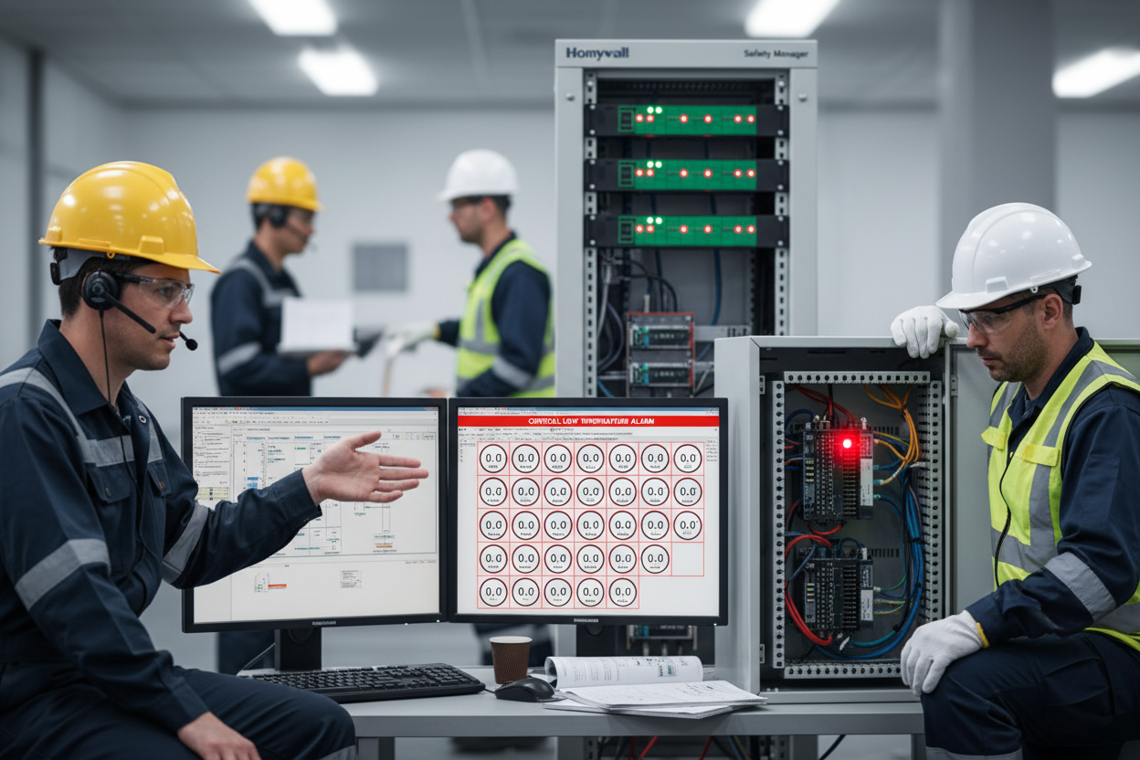
Temperature multiplexer failure is one of the most disruptive fault scenarios in process plants. When 18 temperature transmitter tags simultaneously dropped to 0°C on the PLC display, the operations team initially treated it as a localized instrumentation fault. However, the same failure pattern had been intermittent for two days before becoming permanent. This article reconstructs the event, analyzes the failure chain, and identifies the corrective actions that prevented a more serious safety incident.
The plant used Phoenix Contact temperature multiplexer modules to aggregate RTD and thermocouple signals from multiple field instruments before transmitting data to the PLC. Each MUX unit handled 18 temperature tags. The control platform — a Honeywell Safety Manager SC S300 SIL3 Safety Controller — processed these inputs for process monitoring and protective shutdown logic.
First, understand the architecture: the temperature MUX is not a simple terminal block. It conditions analog signals, performs conversion, and communicates with the PLC over a digital fieldbus. A fault anywhere in the MUX disrupts all 18 channels simultaneously.
Phase 1: Intermittent Faults Signal a Developing Problem
Two days before the shutdown, operators noticed that 18 temperature tags were intermittently showing 0°C for a few seconds before returning to normal. The operations team logged the events but continued normal operations while waiting for the instrumentation team to investigate. This delay was the first critical decision point.
Intermittent faults on a MUX unit indicate internal hardware degradation — typically a failing power supply, a loose backplane connector, or developing firmware instability. Each intermittent event is a precursor to total failure, not a benign glitch.
Moreover, 18 of those same tag slots were already reading 0°C due to a separate pre-existing issue. When the area 1 MUX went into continuous fault mode, the total count of zero-reading tags jumped to 36. This volume of failed readings overwhelmed the operator’s ability to distinguish genuine process alarms from instrumentation noise.
Phase 2: Field Investigation and the Red LED Diagnosis
The instrumentation engineer obtained a work permit and proceeded to the area 1 temperature MUX. The MUX was powered on, but the red fault LED was illuminated. A power reboot did not clear the fault — the red LED returned immediately after restart. A persistent fault LED that survives a power cycle indicates internal hardware failure rather than a communication timeout.
- Step 1: Check the DC power supply voltage at the MUX input terminals. Low voltage causes unstable operation and persistent fault flags.
- Step 2: Inspect the module seating. Vibration-induced looseness on backplane connectors is a frequent cause of intermittent signal loss on multi-channel modules.
- Step 3: Read the MUX diagnostic LEDs against the manufacturer’s fault code table. Phoenix Contact modules use LED patterns to encode specific fault categories including power failure and internal processor errors.
- Step 4: Attempt a firmware-level reset using the module’s hardware reset button before declaring the module faulty.
In this case, the MUX failed all four checks. The team correctly declared it faulty and retrieved a pre-configured spare unit from stores.
Phase 3: The Cascade — Area 2 MUX Failure During Replacement
While the engineer was replacing the area 1 MUX, the area 2 temperature MUX also dropped all 18 of its tags to 0°C. The engineer rushed to area 2. All diagnostic indicators on the area 2 MUX appeared normal. Powering the unit off and back on caused the area 2 tags to recover immediately.
This is the most critical observation in the incident. Area 2 MUX restored itself after a simple reboot while area 1 required hardware replacement. The near-simultaneous failure of both units points to a shared upstream cause — most likely a common power supply or a network event that stressed both units at the same time.
Therefore, the investigation must trace the common power supply feeding both MUX cabinets and verify voltage stability under full load. A power supply with marginal regulation may deliver adequate voltage at light load but sag under full load, triggering fault conditions on multiple modules simultaneously.
The Honeywell S300 FC-SCNT01 Safety Controller Module processed all 36 simultaneous zero readings as genuine low-temperature conditions. This triggered protective logic and initiated the plant shutdown sequence. The safety system performed correctly — it responded to the data it received. The failure was in the instrumentation layer, not the safety system.
Preventive Measures and Protocol Updates
- Step 1: Treat intermittent MUX faults as hardware degradation events. Schedule replacement during the next available maintenance window, not after total failure occurs.
- Step 2: Maintain pre-configured spare MUX units for each module type in service. Configuration time during an emergency increases downtime and the risk of misconfiguration errors.
- Step 3: Add MUX diagnostic outputs to the PLC monitoring system. Most modern Phoenix Contact multiplexers provide a health status signal that the PLC can monitor and alarm on before total failure occurs.
- Step 4: Audit power supply quality to MUX cabinets annually. Measure voltage under full load and verify ripple levels against the manufacturer’s input specification.
- Step 5: Configure PLC input validation to detect sudden mass transitions to zero across a single MUX. This pattern indicates instrumentation failure and should trigger a different alarm class than genuine process low-temperature alarms, giving operators clear context before taking action.
Finally, validate spare unit inventory against the current installed base after every maintenance cycle. Module hardware revisions may require firmware updates before a spare unit can replace a current-generation installed unit without causing communication errors.
Conclusion and Action Advice
Temperature multiplexer failures cascade rapidly into plant shutdowns when many sensor inputs concentrate on single hardware modules. This incident shows that intermittent faults are reliable warnings of impending hardware failure. Instrumentation teams must respond to the first intermittent event with hardware replacement, not continued observation. Pre-configured spares, PLC-level MUX health monitoring, and periodic power supply audits are the three most effective preventive measures against this failure type. Reviewing the power distribution architecture shared between multiple MUX units is essential after any simultaneous multi-unit fault event.
Author: Liu Weicheng is an industrial automation engineer with over 10 years of experience in PLC, DCS, and control systems.


