Pressure Gauge Calibration Using a Comparator: Procedure, Error Analysis, and Hysteresis Checks
Understanding the Comparator Method
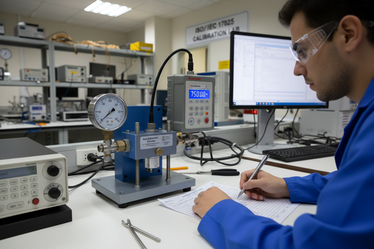
A pressure comparator generates and holds stable pressure simultaneously at the test gauge and the master gauge. First, the comparator applies pressure through a hydraulic or pneumatic fluid. Second, both gauges read the same applied pressure. The difference between the test gauge reading and the master gauge reading defines the error at each test point. Moreover, by testing ascending and descending pressure points, technicians can quantify hysteresis — the difference between upscale and downscale readings at the same nominal pressure. High-accuracy electronic pressure transmitters such as the Yokogawa DPharp EJA Series Pressure Transmitter are commonly used as master reference instruments in comparator calibration setups due to their traceable accuracy and HART output.
Equipment Setup and Safety
Select a comparator rated for the full-scale pressure of the gauge under test. For example, a 0 to 1000 psi ABB gauge requires a comparator capable of generating at least 1000 psi with fine resolution. Mount the master gauge on one port and the test gauge on the opposite port. Ensure both connections are leak-tight before proceeding. Furthermore, verify that the master gauge holds a valid calibration certificate traceable to a national metrology institute. On Emerson Rosemount reference pressure modules, check the calibration sticker date before each use. Always wear safety glasses when pressurizing hydraulic comparators above 500 psi.
Step-by-Step Calibration Procedure
- Step 1: Record the zero reading of the test gauge with no pressure applied. If the pointer does not rest at zero, note the offset as the zero error.
- Step 2: Apply pressure slowly to reach 25% of full scale. Allow the pressure to stabilize for at least 30 seconds. Record both the master gauge reading and the test gauge reading.
- Step 3: Increase pressure to 50%, then 75%, then 100% of full scale. Record both readings at every point.
- Step 4: At 100%, hold pressure for one minute to check for leaks. Any pressure drop indicates a fitting leak, not a gauge error.
- Step 5: Decrease pressure slowly back through 75%, 50%, and 25%. Record both readings on the descending run.
- Step 6: Return to zero pressure and record the final zero reading.
- Step 7: Calculate the error at each point by subtracting the master gauge reading from the test gauge reading.
- Step 8: Compute the hysteresis error at each intermediate point by subtracting the descending reading from the ascending reading.
Error Tolerance and Adjustment
General-purpose Bourdon tube gauges typically carry an accuracy grade of ±1% of full scale. Test gauges used for reference must be at least four times more accurate. Therefore, a grade A gauge requires a master gauge accurate to ±0.25% or better. The Yokogawa EJA530E Gauge Pressure Transmitter with its DPharp silicon resonant sensor provides the sub-0.1% accuracy required for master reference service in gauge calibration applications.
If the error at any point exceeds the allowable tolerance, first check for zero shift. A uniform offset across all points usually indicates a zero adjustment problem. However, errors that increase proportionally with pressure suggest span drift or Bourdon tube deformation. In such cases, replace the gauge rather than attempt field adjustment on sealed Bourdon tube models. ABB pressure gauges with welded Bourdon tubes are factory-sealed and not field-adjustable.
Common Field Problems
Repeatability failures often stem from contaminated comparator fluid. Particles trapped in check valves cause pressure fluctuations during stabilization. Moreover, overtightened gauge connections can distort the socket threads, introducing mechanical binding in the Bourdon tube linkage. Always use a wrench on the gauge hex, never on the case. On Emerson Rosemount electronic reference modules, low battery voltage can cause unstable readings. Replace batteries before each calibration session if the module has been in storage for over 90 days.
Conclusion and Action Advice
Pressure gauge calibration requires more than a single-point check. Test the full span at 25% intervals in both ascending and descending directions. Quantify hysteresis and zero shift before accepting or rejecting a gauge. Finally, always use a master gauge with valid traceable certification, and file complete records for audit readiness. Proper calibration protects process quality and plant safety.
Author: Zhang Hao is an industrial automation engineer with over 10 years of experience in PLC, DCS, and control systems.


