فاندیشن فیلدباس H1: طراحی و راهاندازی بخش
چرا Foundation Fieldbus H1 اهمیت دارد
Foundation Fieldbus (FF) H1 بلوکهای عملکردی را در داخل دستگاههای میدانی اجرا میکند. PROFIBUS PA و HART تنها مقادیر اندازهگیری را منتقل میکنند و کنترل را در میدان اجرا نمیکنند. در یک سیستم آتش و گاز، اجرای منطق در دستگاه میدانی باعث حذف تأخیر رفت و برگشت میشود. عملکرد کنترل حتی در صورت قطع ارتباط با میزبان ادامه مییابد. به همین دلیل FF H1 هنوز برای حلقههای SIL-2 و SIL-3 مشخص شده است.
طراحی بخش FF H1 نیازمند محاسبه بودجه توان است. یک بخش از یک منبع تغذیه اصلی ۴ تا ۱۶ دستگاه را تغذیه میکند. اگر بودجه توان بیش از حد باشد، دستگاههای انتهای دور روشن نخواهند شد. Emerson DeltaV و Yokogawa Stardom دو پلتفرم DCS رایج برای FF H1 امروزه هستند. ماژول ارتباطی Yokogawa ALF111-S00 رابط Foundation Fieldbus H1 را برای سیستمهای DCS CENTUM Yokogawa فراهم میکند، در حالی که ماژول تغذیه Yokogawa NFPW444-10 توان ۲۴ ولت DC تنظیمشده مورد نیاز برای عملکرد پایدار FF H1 را تأمین میکند.
محاسبه بودجه توان
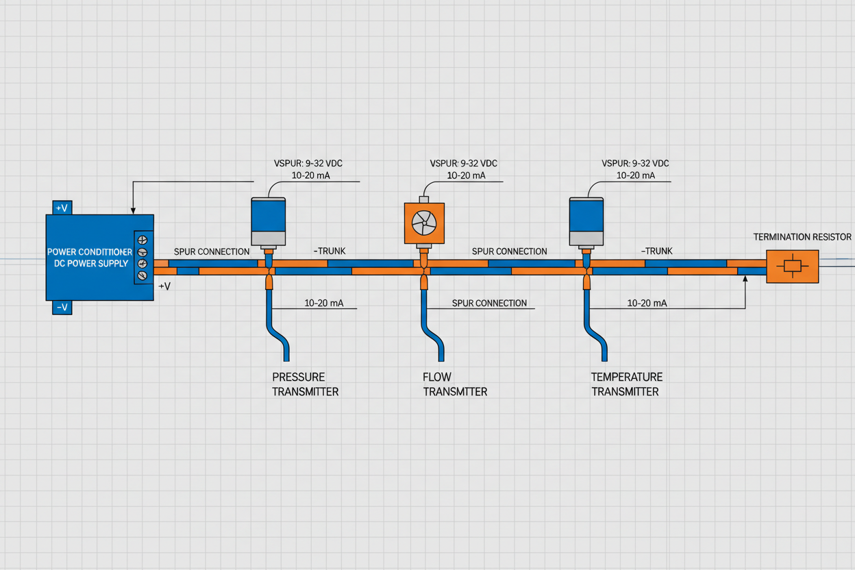
افت ولتاژ علت اصلی خرابی بخش است. بخش در ولتاژ نامی ۲۴–۳۲ ولت DC کار میکند. هر دستگاه ۱۰–۲۵ میلیآمپر جریان میکشد. ولتاژ در دستگاه نباید کمتر از ۹ ولت DC، حداقل FF H1، باشد.
قبل از نصب بودجه را محاسبه کنید: جریان کل = مجموع جریانهای سکون دستگاهها + ۱۰٪ حاشیه. افت ولتاژ = جریان کل × مقاومت حلقه. مقاومت حلقه = ۲ × طول کابل × مقاومت به ازای هر متر. برای کابل جفت پیچخورده ۱۸ AWG، مقاومت ۰.۰۲۱ اهم بر متر است. برای ۲۰۰ متر و ۱۲ دستگاه با جریان ۱۵ میلیآمپر، افت ولتاژ ۱.۵۱ ولت است — ولتاژ دستگاه ۲۲.۵ ولت است که بهطور قابل توجهی بالاتر از ۹ ولت است.
جریان راهاندازی را در نظر بگیرید: برخی دستگاهها هنگام روشن شدن ۵۰ میلیآمپر به مدت ۵۰ میلیثانیه جریان میکشند. یک تنظیمکننده توان با راهاندازی نرم از جریان راهاندازی همزمان جلوگیری میکند. Emerson KJ3002X1-BA1 و Yokogawa PW302 هر دو دارای راهاندازی نرم هستند که جریان راهاندازی را به ۳۵۰ میلیآمپر در هر بخش محدود میکند.
راهاندازی مرحله به مرحله
- مرحله ۱: پیوستگی کابل و عایقبندی را بررسی کنید. مقاومت حلقه باید برای ۵۰۰ متر کمتر از ۵۰ اهم باشد. مقاومت عایق باید در ۵۰۰ ولت بیش از ۱۰۰ مگااهم باشد.
- مرحله ۲: تنظیمکننده توان را وصل کنید. خروجی را روی ۲۴ ولت DC تنظیم کنید. در ترمینالها اندازهگیری کنید — باید ۲۴.۰ ± ۰.۵ ولت DC باشد. یک مقاومت ۵۰۰ اهمی برای شبیهسازی بار وصل کنید. ولتاژ نباید زیر ۲۳.۵ ولت بیاید.
- مرحله ۳: دستگاهها را از نزدیکترین به دورترین وصل کنید. پس از هر اتصال ۳۰ ثانیه صبر کنید. جریان بخش را بررسی کنید. Yokogawa YTA310 جریان ۱۸ میلیآمپر میکشد. Emerson 3051S FF جریان ۲۲ میلیآمپر میکشد. اگر جریان افزایش نیافت، قطبیت سیمکشی را بررسی کنید.
- مرحله ۴: آدرسهای دائمی اختصاص دهید. دستگاهها با آدرسهای موقت (۱۷–۲۵۴) روشن میشوند. آدرسهای دائمی ۱–۱۶ را اختصاص دهید. فایل قابلیت (CFF) را از رجیستری Fieldbus Foundation برای هر دستگاه دانلود کنید.
- مرحله ۵: بلوکهای عملکردی را زمانبندی کنید. ماکروسیکل را برای بیشتر حلقهها روی ۵۰۰ میلیثانیه و برای حلقههای سریع روی ۱۰۰ میلیثانیه تنظیم کنید. ترتیب اجرا را تأیید کنید: ابتدا بلوکهای ورودی، سپس بلوکهای کنترل و در نهایت بلوکهای خروجی.
تشخیص خطاهای ارتباطی
- خرابی کامل بخش: هیچ دستگاهی ارتباط ندارد. LED تنظیمکننده توان را بررسی کنید — قرمز نشاندهنده جریان بیش از حد یا اتصال کوتاه است. همه دستگاهها را جدا کنید و مقاومت به زمین را اندازهگیری کنید. کمتر از ۱۰۰۰ اهم نشاندهنده اتصال کوتاه است. وجود آب در جعبههای اتصال را بررسی کنید.
- قطع و وصل شدنهای متناوب دستگاهها: ولتاژ بخش را در دستگاه با مولتیمتر اندازهگیری کنید. کمتر از ۱۲ ولت باعث ریست متناوب میشود. اگر ولتاژ کافی است، تداخل VFD را بررسی کنید — کابل FF H1 را حداقل ۳۰۰ میلیمتر از کابلهای VFD دور کنید.
- خطای مقاومت ترمینیشن: FF H1 نیاز به ترمینیشن ۱۰۰ اهم در هر دو انتهای بخش دارد. تنظیمکننده توان دارای ترمیناتور داخلی است. مقاومت DC را در سراسر بخش با جدا بودن تنظیمکننده توان اندازهگیری کنید — باید ۵۰ اهم باشد (دو مقاومت ۱۰۰ اهم موازی). هر انحراف نشاندهنده ترمیناتور گمشده یا آسیبدیده است.
- خطاهای بلوک عملکردی: به صورت «Block Alarm» در DCS ظاهر میشوند. استفاده از ماکروسیکل را بررسی کنید. اگر بیش از ۸۰٪ باشد، بلوکهای عملکردی را کاهش دهید یا دوره ماکروسیکل را افزایش دهید. دستگاههای کند را تعویض کنید یا بلوکهای آنها را به DCS منتقل کنید.
نتیجهگیری و توصیههای عملی
بخشهای Foundation Fieldbus H1 نیازمند طراحی دقیق بودجه توان، زمانبندی صحیح بلوکهای عملکردی و مسیرکشی مناسب کابل هستند. افت ولتاژ را برای دورترین دستگاه محاسبه کنید. از تنظیمکننده توان با راهاندازی نرم استفاده کنید. بلوکها را به ترتیب ورودی-کنترل-خروجی زمانبندی کنید. یک تنظیمکننده توان FF H1 و ترمیناتور یدکی برای هر منطقه کارخانه نگه دارید. یک بخش FF H1 بهخوبی طراحیشده، مقاومت کنترل در سطح میدانی را ارائه میدهد که هیچ حلقه ۴–۲۰ میلیآمپر متداولی نمیتواند با آن رقابت کند.
نویسنده: ویجیا چن، مهندس اتوماسیون صنعتی با بیش از ۱۰ سال تجربه در PLC، DCS و سیستمهای کنترل.


